The bypass capacitor is seen on almost every amp out there but is it really necessary? As in many text book, it serve 2 purpose:
1. Act as short to ground at high frequency which shunt noise from other noise source that couple into the power supply through the power supply trace.
2. Act as a power source for fast transient current at high frequency.
But in reality, i see many amps connect the power supply directly to the V+ or V- leg of the opamp, if we want to maximize effect (1), it should be power supply -> bypass cap -> ic legs. So i think most of the time, the bypass cap is there to serve for purpose (2) but, here is the impedance plot of a 0.1uf x7r capacitor from kemet:

You can see that at audio frequency, the impedance of the capacitor is very high, so when a "high" frequency audio signal need to be produce by the amp, the current should flow from the power supply because it has much lower output impedance at audio frequency, not the capacitor. The capacitor is only good at 1->100Mhz which is far above audio frequency. So what is the real benefit of a by pass capacitor?
1. Act as short to ground at high frequency which shunt noise from other noise source that couple into the power supply through the power supply trace.
2. Act as a power source for fast transient current at high frequency.
But in reality, i see many amps connect the power supply directly to the V+ or V- leg of the opamp, if we want to maximize effect (1), it should be power supply -> bypass cap -> ic legs. So i think most of the time, the bypass cap is there to serve for purpose (2) but, here is the impedance plot of a 0.1uf x7r capacitor from kemet:
You can see that at audio frequency, the impedance of the capacitor is very high, so when a "high" frequency audio signal need to be produce by the amp, the current should flow from the power supply because it has much lower output impedance at audio frequency, not the capacitor. The capacitor is only good at 1->100Mhz which is far above audio frequency. So what is the real benefit of a by pass capacitor?
No it isn't. It is more common than it should be, I grant you.proid said:The bypass capacitor is seen on almost every amp out there
The main benefits of a bypass capacitor are:
1. impresses audio journalists and hence customers who do not understand electronics
2. possibly inserts a notch above the audio range, which if audible will be misinterpreted as an improvement in sound
3. allows use of a greater number of expensive components - see benefit 1
There are situations where a suitable extra decoupling capacitor is useful, but this will usually not be straight across a bigger capacitor but mounted right at the item which needs the decoupling.
> capacitor is only good at 1->100Mhz which is far above audio frequency.
You think the chip is for audio.
The CHIP does not know that, and many good audio chips have gain far into MHz. Also declining PSRR at high frequency. So any output jiggle gets to the supply and back to the rails, then into the chip to be amplified again.
Putting some compact capacitance near the chips (or high-performance discrete) is just good hygiene. Like washing the table even if you use plates.
So what is the real benefit of a by pass capacitor?
A circuit is not just the schematic. http://www.analog.com/media/en/training-seminars/tutorials/MT-101.pdf
Last edited:
As noted above, supply impedance is in general way lower than that of any reasonable bypass capacitor value (unless you use *huge* ones, comparable to main supply filters that is), but many forget that said supply is at the far end of wires or tracks.
You can often ignore them, but gain not in many cases.
There is a reason for the customary .047 or .1 *ceramic* bypass cap "as close as possible to chip or even discrete amp feed legs".
Also *where* to bypass to needs careful consideration.
You can often ignore them, but gain not in many cases.
There is a reason for the customary .047 or .1 *ceramic* bypass cap "as close as possible to chip or even discrete amp feed legs".
Also *where* to bypass to needs careful consideration.
The "groundplane" solution shown as having the lowest impedance over the widest range of frequencies is described and shown in a paper (which I can't find), where the "ground plane" is a sheet of thin copper foil over the top of the DIP IC and connected directly to the "ground" lead of the IC. The decoupling cap is shown as attached to the IC power lead and laid flat on top of the copper plane where it is soldered on with near zero length lead outs.
I think the paper was written before SMD capacitors became available.
Basically what the author was implementing is a copper plane that allows the decoupling current to "follow" the route of the current/s inside the IC thus minimising the LOOP AREA and minimising the inductance.
Now for me the big question becomes:
Is the top mounted copper foil closer to the internal current routes than the in board copper foil that forms the integrated ground plane?
Whichever conductive plane is closer to the in IC currents will give the lower impedance and thus the better decoupling.
SMD ICs lying directly on top a ground plane with decoupling directly between power pin and ground plane are the ultimate version of this as shown in the link.
Last edited:
i know nothing but i thought adding bypass caps on opamps was to help with oscillation?
Almost all amplifier ICs [and many other circuits] need some kind of local bypass capacitor, and most of their
data sheets mention this. Without one, performance would be dependent upon the layout and components
chosen, if the circuit works at all. Certainly oscillation is one possibility.
https://e2e.ti.com/blogs_/archives/b/thesignal/archive/2013/04/23/bypass-capacitors-yes-but-why
The problem we have is that in audio the term 'bypass cap' means two rather different things:
1. any film cap placed in parallel with any electrolytic cap (or sometimes a larger film cap), in the mistaken belief that this will improve something
2. a suitable cap (often ceramic) placed at a circuit location where low HF impedance is needed, in the sure knowledge that this will improve something
Look at the This video
It shows the effect in a circuit in a practical way
www.youtube.com/watch?v=9EaTdc2mr34
It shows the effect in a circuit in a practical way
www.youtube.com/watch?v=9EaTdc2mr34
Hello All,
At present I am looking carefully at decoupling capacitor arrangements for a DAC project.
For digital I am using 1uF multilayer X7R ceramic - physically close to each IC.
(The 1uF has the same physical dimensions as the 0.1uF typically used for digital decoupling (same inductance), but the ESR minimum point now coincides with the latching frequency of the logic) ... better decoupling in my opinion.
For analogue decoupling (op-amps etc. ) I might choose again multilayer ceramics 10uF physically close to the ICs.
The purpose here is to avoid oscillation complications with multiple capacitor bypassing arrangements, to keep impedance small and to provide a suitable local reservoir.
Now the questions...
Digital : Am I on the right track with my digital reasoning?
Analogue : Why the normal need for bypassing 10uF electrolytic with 0.1uF ceramic when a 10uF ceramic will do?
I do worry about assumptions about the 'sound' produced by components constructed from different materials (some exotic) . e.g. carbon will sound 'blacker' silk will sound soft, ceramic will sound brittle. Are there any views on singular large (capacitance value) ceramics to replace bypassed electrolytics?
Your thoughts please...
Last edited:
For the digital side of my dac chips I always use a solid polymer type, around 100uf, since the higher values tend to have a super low esr. Maybe use a small ceramic if the inductance of the circuit will allow it without resonance, or just leave out the ceramic and keep the solid polymer as close to the dac chip as possible.
For the analog supply I have realized some decent gains from leaving the small bypass out, using instead a good quality 4.7uf 50v electrolytic in their place. Of course this goes against all the datasheets that call out a .1uf bypass on everything, don't know what to say about that; Your results may vary.
For the analog supply I have realized some decent gains from leaving the small bypass out, using instead a good quality 4.7uf 50v electrolytic in their place. Of course this goes against all the datasheets that call out a .1uf bypass on everything, don't know what to say about that; Your results may vary.
Digital : Am I on the right track with my digital reasoning?
Analogue : Why the normal need for bypassing 10uF electrolytic
with 0.1uF ceramic when a 10uF ceramic will do?
From the horses' mouths, but the physical implementation is key.
http://www.ti.com/lit/an/scba007a/scba007a.pdf
http://www.ti.com/lit/an/sloa069/sloa069.pdf
http://www.analog.com/media/en/training-seminars/tutorials/MT-101.pdf
The problem we have is that in audio the term 'bypass cap' means two rather different things:
1. any film cap placed in parallel with any electrolytic cap (or sometimes a larger film cap), in the mistaken belief that this will improve something
2. a suitable cap (often ceramic) placed at a circuit location where low HF impedance is needed, in the sure knowledge that this will improve something
There are 2 stages in bypass capacitor usage in circuit designers.
1- Before you know how to solve it mathematically. Aesthetics dominates. It's about how good the capacitor looks in the board, chassis or wiring. Many electronically absurd but pleasant choices result, the worse is when proudly adding a capacitor causes a dip at one frequency of less significance but as a side effect it causes a peak at another frequency of more significance.
2- After you know how to model and solve the problem mathematically, with the help of software simulations, datasheets, and rules of thumb for figuring out all R,L,C involved. Then it can get as ingenious as cancelling one resonance coming from some design compromise with other resonance coming from another design compromise. This is "level God".
I used to do that with springs; one resonance is mostly cancelled by the different frequency of another spring when working in tandem. Rubber helps in certain quantities too; passive damping.
Most of my dac projects look like they have been dipped in glue, then shaken around in my spare parts bin for a while, but I know what you mean regarding aesthetics. I think it was the Audio GD products that were that way when I first noticed that the colorful display of parts didn't always make sense to me.
I've come to the conclusion that with bypassing, there is going to be some trial and error to tend to potential resonance.
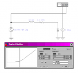
Lets introduce some common elements (attached pictures in order):
- The PCB trace (or wire). Inductance calculator (valid for the case where there is a ground plane, inductance values are much higher without ground plane or for wires): https://www.allaboutcircuits.com/tools/microstrip-inductance-calculator/
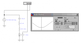
- The low ESR electrolytic capacitor.
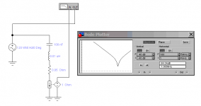
- The small thru-hole film or ceramic capacitor.
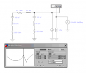
- Capacitors interacting through PCB traces.
Thru-hole capacitor inductance is about 1nH per mm of lead separation. About 1~2nH for SMD depending on length to width ratio.
Impedance is the figure being plotted in all cases. Peaking translates into ringing or oscillation as seen on oscilloscope. Simulation software used is old Electronics Workbench 5.12 (abandonware).
- The PCB trace (or wire). Inductance calculator (valid for the case where there is a ground plane, inductance values are much higher without ground plane or for wires): https://www.allaboutcircuits.com/tools/microstrip-inductance-calculator/
- The low ESR electrolytic capacitor.
- The small thru-hole film or ceramic capacitor.
- Capacitors interacting through PCB traces.
Thru-hole capacitor inductance is about 1nH per mm of lead separation. About 1~2nH for SMD depending on length to width ratio.
Impedance is the figure being plotted in all cases. Peaking translates into ringing or oscillation as seen on oscilloscope. Simulation software used is old Electronics Workbench 5.12 (abandonware).
Attachments
Last edited:
Some additional explanation here, scroll down to page 18 or so...
http://www.murata.com/~/media/webrenewal/support/library/catalog/products/emc/emifil/c39e.ashx
http://www.murata.com/~/media/webrenewal/support/library/catalog/products/emc/emifil/c39e.ashx
- Status
- Not open for further replies.
- Home
- Amplifiers
- Power Supplies
- Bypass capacitor theory