Hi Guys,
Yes, it is an old question. I have two grounding scheme as attached pic, A and B.
''A'' scheme: It is popular way, many project in this 4rum use that. Ground of decoupling caps, capacitance multiplier will joint with signal ground at star ground.
''B'': It usually be seen in Japanese amps. And Japanese amps is quite good. Ground from input go series through stages and joint at ''star ground''
But i wonder, what kind will better, will lower noise/hum levels?! Or suggest me another something better.
Any answer is welcome.
Regard,
Thanks, Walkalone.
Attachments
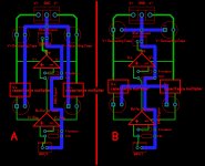
'A' is not star ground. The buffer op-amp capacitors are sharing same trace as main amp capacitors, and the distance between buffer op-amp capacitor and buffer op-amp is too large that it defeats the purpose of having capacitors physically close. Worse still, output ground is right in between signal ground and power capacitor ground. Your signal ground is going to move up and down and the capacitors can't save it.
'B' makes more sense - it's a 'star of stars', and often makes sense in terms of feasibility, or sometimes when some isolation between the grounds is intended or beneficial or does not have too much drawback. The current loop between buffer op-amp capacitor and buffer op-amp is smaller.
There is also option 'C' : a big ground plane
Also, you're missing feedback capacitors between output and inverted input
Thanks for your detail answer,
I'm trying to make best grounding follow usual way - not ground plane. Reason for that is i have seen few commercial products that is not used ground plane but they have incredible SNR levels. So, i want to make similar something.
That pic just for easy understand, easy imagine what i want to say, therefore there is no feedback capacitor.
Back to ''B'', what i can do to make it better?
Regard,
Walkalone,
Typo - feedback resistors

Audio does not require much performance - unless you're getting significant worse SNR than the chipamp's datasheet, LM3886 is 92dB for example - there is no need to think too much of PCB layout.
Audio does not require much performance - unless you're getting significant worse SNR than the chipamp's datasheet, LM3886 is 92dB for example - there is no need to think too much of PCB layout.
For common-ground multi-channel devices, say devices which need star grounding, lo-resistance paths between all power devices, some of which are non-linear (harmonic and or reactive, such as supply capacitors and non-Class-A amplifiers) are important in order to avoid hum and clang. Stereo amps often have both power channels layed closely around main capacitors, so resistances are small.
For single-channel devices, which are not earthed or earthed at one point only, and multi-channel devices with galvanically isolated inputs, a hierarchical grounding scheme as in B is o.k., as ground loops cannot occur.
Electronically symmetrical signals such as put out by bridged amplifiers and received by instrumentation amplifiers may help with hum but introduce hi-frequency interference due to ground and earth loops, common with switching power supplies.
...There is also option 'C' : a big ground plane...
I concur with wwenze. You should simply 'pour' a ground plane on the PCB layout. A ground plane would induce the least amount of ground-loop type noise.
Walkalone may want no PCB, even tho he uses a layout software. As soon as two PCBs or metal chassis' are to become connected, the grounding problem re-appears.
Thanks all,
I interested for this issue because i'm trying to find best grounding scheme that get lowest noise and keep it for reference to layout design.
Ground plane is OK, however a well ground plane design is quite hard. I thinks good design that also must same as Japanese style as above. It require the arrangement of ground, do not mix between input ground & output ground, ground of stages, supplies...etc. Ground plane just only for discard inductance of single traces.
If you like playing with layout, then lay out individual traces that form their own functional current flow loops. Use the decoupling cap pads as the star centre point for each circuit loop that interacts with that cap. Imagine that only that trace takes the current to the circuit node you are powering.
Eg. your V+ cap pos pad is star centre with 3 individual traces going to power socket, amp pos, buffer decoupling cap. Your V+ cap neg pad has individual star traces going to power socket, amp Rin/f/b, buffer decoupling cap.
Eg. your V+ cap pos pad is star centre with 3 individual traces going to power socket, amp pos, buffer decoupling cap. Your V+ cap neg pad has individual star traces going to power socket, amp Rin/f/b, buffer decoupling cap.
- Status
- Not open for further replies.
- Home
- Amplifiers
- Power Supplies
- Grounding Scheme