Howdy. I have a question related to the overall typology Mark was looking to deploy here.
I have an "auxiliary PSU" which supplies +12/-12V to a "main controller unit". The main controller unit (MCU) takes care of all the housekeeping functions of the amp (it is designed by diyAudio member ASTX) such as DC monitoring, in-rush relay control, output relay control, power on/standby etc.
The MCU controls the supply of +12V/-12V to input boards (balanced to SE conversion), +12V to inrush relays and +12V to output relays. GND from each of these is returned back to the MCU "power ground" and on back to the aux PSU via the GND wire between the two boards. The controls/switches on the MCU for the relay and input board supply are either MOSFETs (control via gate) or an opto MOSFET driver (VOM1271) so there is no interconnection between the control side of the MCU and the relays/aux power supply. I have segregated the ground planes on this MCU board into "power ground" and "signal ground". The board has provision to connect them via a 1206 resistor (and I used 10R for testing the board). The MCU operates at 5V via an SMD regulator IC fed 12V from the power side.
The "signal ground" side of the MCU is connected to the amp's star ground for each of left and right, respectively, via 22 ohm resistors. This connection to the amp's star ground is needed for DC monitoring.
My question relates to how to properly connect the ground of the aux PSU to the rest of the amp, if at all. I was initially thinking that this supply and return of voltage/current to input boards and relays was a closed system and needn't be connected to the amplifier's ground anywhere. The aux PSU ground will be "dirty" as it contains rectifier pulses etc from mains AC to DC conversion and subsequent regulation. I was thinking the aux supply could float or merely be connected to chassis with no direct connection to the amp's signal ground. But this segregation/independence is broken by the 5V feed to the PIC controller which manages all of the functions MCU.
I am wondering if indeed I need to connect Aux supply GND to the rest of the amplifier and, if so, how best to do so. I can (a) deploy the resistor built into the MCU board which would connect the aux supply ground to the MCU 'signal' ground and on to the amp's signal ground via the parallel 22R (b) connect it directly to amp star ground left and right (either directly or via resistors) or (c) connect to chassis (the amp's star ground is connected to chassis via 10R 0.1uF).
Thoughts? (Hopefully the above description makes sense.)
the need for the question comes from the confusion of using the "ground" word.
Going back to your statement:
Then you add:
That is not the way to approach current routing.
EVERY connection is a TWO WIRE connection where the current flows from the Source and Returns to the Source.
You layout your wiring to comply with this mandatory Flow and Return.
And keep the two wire Flow and Return as a close coupled pair. Do not take the Return to some remote location.
Now go back to your layout of modules and LOOK at where your Flow routes are and put in the complementary Return routes alongside them to make that close coupled low loop area TWO WIRE connection.
When that is complete you will probably find that 95% of your wiring is already in place.
That's when you next look for what has been omitted to allow the system to work.
Going back to your statement:
there is no mention of the route for return current.which supplies +12/-12V
Then you add:
where it becomes clear that your are using a remote "ground" and hoping that will solve all your routing problems.GND from each of these is returned back to the MCU "power ground" and on back to the aux PSU via the GND wire between the two boards.
That is not the way to approach current routing.
EVERY connection is a TWO WIRE connection where the current flows from the Source and Returns to the Source.
You layout your wiring to comply with this mandatory Flow and Return.
And keep the two wire Flow and Return as a close coupled pair. Do not take the Return to some remote location.
Now go back to your layout of modules and LOOK at where your Flow routes are and put in the complementary Return routes alongside them to make that close coupled low loop area TWO WIRE connection.
When that is complete you will probably find that 95% of your wiring is already in place.
That's when you next look for what has been omitted to allow the system to work.
there is no mention of the route for return current.
I said:
GND from each of these is returned back to the MCU "power ground" and on back to the aux PSU via the GND wire between the two boards.
The connection between Aux Supply and MCU Power Ground is a 3-wire connection: +12V, -12V and 0V "ground". The return current is either via the ground wire from a relay to MCU power ground and onward back to the aux supply's ground via the 3 wire connection between the two boards or, in the case of the input boards, via the -12V (and power GND wire for the supply caps - this input board 0-volt supply return is segregated from the input board signal ground) heading back to the MCU power ground and onward back to the aux supply board. And, yes, I understand that every connection is a two-wire connection. All are close coupled pairs. (An input board's main ground plane is signal ground and each input board's ground plane is connected to the respect channel's star point.)
The exception, as noted, is the supply of +5V to the control side of MCU. This side of the MCU is necessarily connected to the amp signal ground at the star point (via two 22 ohm resistors as it is connected to each of the left and right star points). Were it not for this, the aux supply voltages/currents and their returns would all be close-coupled pairs from and back to the aux supply (via the power ground side of the MCU board where their switches are located) and completely independent of the rest of the amp. A close-coupled pair philosophy would suggest providing a connection for the MCU 5V supply return to the aux supply via the resistor placeholder between the two ground planes on the board. This, however, connects the aux supply ground to the amp star ground points (because the MCU must be connected to signal ground for DC control). I guess a resistor would provide some means of isolation from the dirty psu ground (although I don't understand how). Does this make sense?
The second part of my question relates to connecting the aux supply 0V plane to the rest of the amp. In a previous version of this build there were two aux supplies, one for each channel, and also the MCU itself had its own supply. The new MCU board has allowed me to optimise all of this into just one aux supply. In that setup, I had connections from each aux PSU to the respective star ground point. But now that things are optimised and I've given it all more thought I can't see the rationale for connecting the aux supply ground plane to the amp star ground scheme (except as just discussed via the resistor connecting the two planes on the MCU board to provide a direct return for the 5V supply to the MCU's PIC chip - with this resistor there is an indirect connection from aux supply ground to the MCU to the amp star points via twin parallel 22 ohm resistors).
Send 6VAC to the MCU board and let it rectify, filter, and regulate with respect to its local ground, creating [+5VDC and GND] at the MCU. Generate a 50 Hz triangle wave (single TL072), LPF the pokey-peaky tips away, and drive that into a 2VA trafo primary using an opamp + 2BJT buffer. Send the secondary to the MCU board.
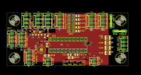
The MCU board is done. Attached is an image of top side to add some perspective. Leftmost plane is "power ground" while rightmost one is connected to amp star/silent ground via 22R||22R (when stereo build) on bottom side and Faston connectors. 12V->5V is done via an IC on bottom layer of board under the three vias. R15 can connect the two planes. On the left you see supply in and then connections for power to input board (aux), in-rush relay control and mute (output relays - up to 4). I'm using one of my 1A fancy regulator circuit boards to generate +12/-12V. The MCU controls onward flow of power to input boards and relays. (I recognise I don't need a fancy supply for relays, but maybe there is a benefit for the input boards plus the supply board was done, almost free and easy to put to use.)
So instead of the previous 3 mains AC pairs running to three transformers and rectifier networks (2 x aux supplies and 1xMCU) I have just one supply. This aux supply is on as long as the rear switch is on. Standby power consumption is leakage in its transformer, the supply regulator circuit itself and a tiny, tiny amount of current used by the MCU while it monitors the front panel power switch. Very likely well less than a watt (I just haven't checked leakage consumption of the regulator board itself). When the front panel power button is turned on then power is provided to input boards, in-rush relays and output relays - all well within the capability of the aux supply.
I'm just stuck on (a) whether to use R15 to provide a direct return path for the 5V for the MCU PIC supply and (b) whether I need a further connection from the aux supply board's ground to the rest of the amp. I was originally thinking R15 would not be populated in use so that the MCU rightmost ground plane which is connected to amp star/silent ground would be totally isolated from the aux supply ground, but I have realised that doesn't provide a return path for the 5V PIC supply unless there is some other path back to aux psu. If I use R15 do I need another connection from my aux supply ground to some other point in the amp (star ground, chassis or none)?
Attachments
Last edited:
- Status
- This old topic is closed. If you want to reopen this topic, contact a moderator using the "Report Post" button.