What do you plan to use to load your regulator circuits.
What is the maximum load voltage, current and power you need.
How can you get 256 resistance values using 8 resistors if 0 ohms
counts as one value? Hint: What mammal has four toes on each paw? or What is the difference between a Hamster wheel and an ohm's law wheel?
50v max and a few hundred mA @45v (is all i initialy wanted) as it would only have be powering univaersal heaters. But, saying that i would like a good range voltage and as much current as poss as i would like a supply that can be used for many different projects at varying volts an amps for anything i might want to throw at it.
The numbers 8 and 256 and 0 make me think of the words 'base two' and 'digital' or 'ladder'. But really i have no idea. Using only resistors?.....Dont know.
Last edited:
Hello WSJ. You are right about the voltage at pin 11. I was thinking about my own circuit, where I need only 30 Volt at Umax, but in the case of jimmiegin, there are a problem here. It would be possible to put a NPN transistor outside the 723, emitter to 0 Volt, base on pin 9, now lifted from 0 Volt, and the collector pulling the base of the PNP pass-driver. There also is needed a resistor from base to emitter, to cause a little quesent current in the internal transistor/zenerdiode, and to take care of the Icb0 current in the extern transistor. There is needed some calculation regarding power dissipation. By using the proposed circuit, it was actually possible to put a 7824 in front of pin 13 of the 723, to limit its supply voltage, and filtering its supply.
Hello all.
Just a quick question about 7818 and 7918. As part of my power supply i would like 45v for universal heaters but would also like a variable supply with a good amount of current (variable limiting). If i where to have a seperate fixed supply in the same case using 7818 and 7918 for dual rail, and elevated the ground pins to give 22.5v on + and - giving 45v. Would That be safe to operate the regulators at that voltage and would it be ok to power universal heaters from a dual rail supply? Then i could have a seperate 0-30v with variable current limiting to 2 amps as soeren poulsen.
Just a quick question about 7818 and 7918. As part of my power supply i would like 45v for universal heaters but would also like a variable supply with a good amount of current (variable limiting). If i where to have a seperate fixed supply in the same case using 7818 and 7918 for dual rail, and elevated the ground pins to give 22.5v on + and - giving 45v. Would That be safe to operate the regulators at that voltage and would it be ok to power universal heaters from a dual rail supply? Then i could have a seperate 0-30v with variable current limiting to 2 amps as soeren poulsen.
50v max and a few hundred mA @45v (is all i initialy wanted) as it would only have be powering univaersal heaters. But, saying that i would like a good range voltage and as much current as poss as i would like a supply that can be used for many different projects at varying volts an amps for anything i might want to throw at it.
The numbers 8 and 256 and 0 make me think of the words 'base two' and 'digital' or 'ladder'. But really i have no idea. Using only resistors?.....Dont know.
Yes, that's brilliant! Your idea to make a universal load is insightful.
A binary resistor load is a great project.
Lets start a project design and determine the specifications for the load.
1. If you start the ladder with 1 ohm what is the total resistance of all 8 resistors in series?
2. Say you have a 5 V power supply and want a load of 5 A, easy 1 ohm @ 25 W would you buy a 25 W resistor?
Hello WSJ. You are right about the voltage at pin 11. I was thinking about my own circuit, where I need only 30 Volt at Umax, but in the case of jimmiegin, there are a problem here. It would be possible to put a NPN transistor outside the 723, emitter to 0 Volt, base on pin 9, now lifted from 0 Volt, and the collector pulling the base of the PNP pass-driver. There also is needed a resistor from base to emitter, to cause a little quesent current in the internal transistor/zenerdiode, and to take care of the Icb0 current in the extern transistor. There is needed some calculation regarding power dissipation. By using the proposed circuit, it was actually possible to put a 7824 in front of pin 13 of the 723, to limit its supply voltage, and filtering its supply.
Those are all great ideas. Let's do a circuit design review. How can the 723 output be configured to drive an NPN with the emitter grounded? You can use Express PCB to make a schematic. Use export schematic image to convert it to a pic.
WJS I have no idea what you are talking about! But I do have an idea that I want some power supply on my workbench. You are obviously far far more educated in electrical engineering and i am just starting so its quite obvious i have no place or understanding in current topic discussion. However i am currently learning from the bottom up, about zener/emitter follower regulators. I would like a schematic that is not a load of rubish , that will work well, that i can build myself (not a kit) etch myself for the expirience, as have only used strip board or point to point with turret for the few pedals and amps i have done. there are many good videos on youtube on the subject of power suplly design. can someone please show me a 0-30v 2a schematic that will work ok, and i will make a seperate supply for the 100mA 45v heater supply. when i know more of what i am trying to speak i will replace them with my own design. Thank you.
Last edited:
WJS I have no idea what you are talking about! But I do have an idea that I want some power supply on my workbench. You are obviously far far more educated in electrical engineering and i am just starting so its quite obvious i have no place or understanding in current topic discussion. However i am currently learning from the bottom up, about zener/emitter follower regulators. I would like a schematic that is not a load of rubish , that will work well, that i can build myself (not a kit) etch myself for the expirience, as have only used strip board or point to point with turret for the few pedals and amps i have done. there are many good videos on youtube on the subject of power suplly design. can someone please show me a 0-30v 2a schematic that will work ok, and i will make a seperate supply for the 100mA 45v heater supply. when i know more of what i am trying to speak i will replace them with my own design. Thank you.
I like your enthusiasm and desire to learn, I will be happy to help you and stimulate your thought process. Limited experience is not a problem, if you want to learn I will help you.
First step, download the Free PCB and Schematic software form expresspcb.com
Follow the schematic tutorial and make a schematic of a Zener emitter follower regulator. All you need is a Zener, resistor and NPN. See what you can do and I will help you if needed.
Zener emitter follower regulators are a great place to start, I have used that circuit as a teaching tool.
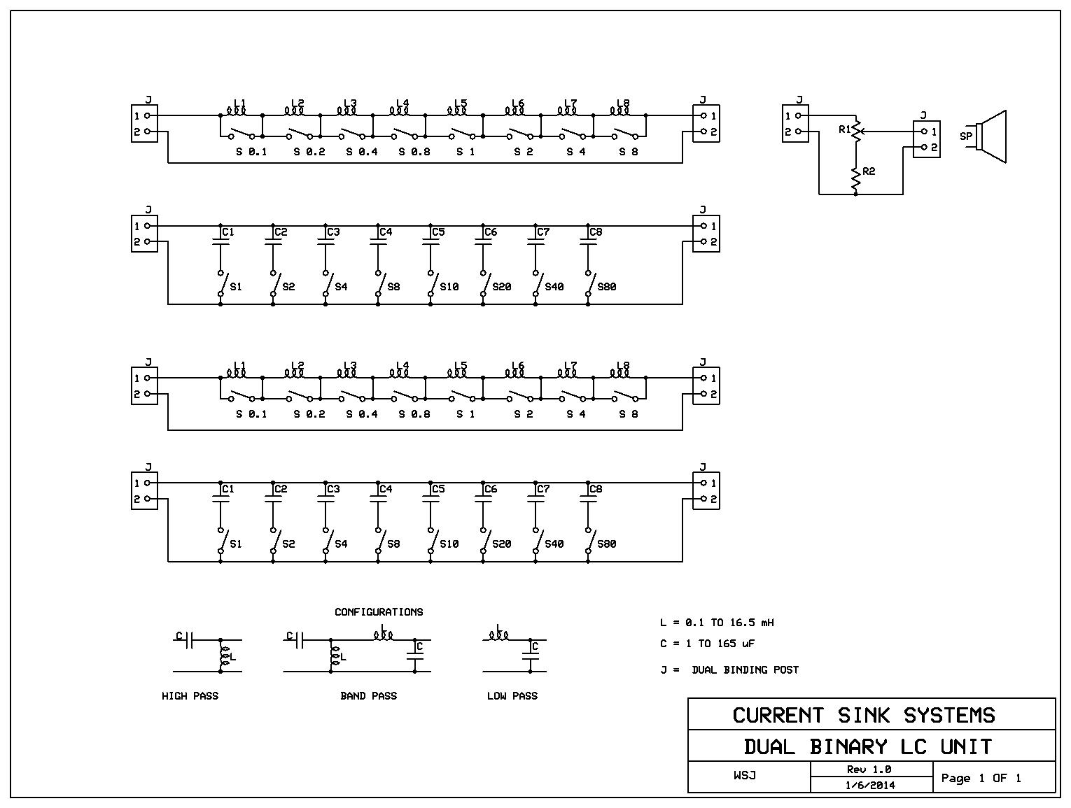
Here is a Schematic using software form express pcb If you replace the inductors with resistors you will have a Binary Load for power supply testing.
The resistor values could be 1,2,4,8,16,32,64. That would give you a load with 255 different values, 1 to 255 ohms.
Dear jimmiegin.
If You want to start building, and have something usefull, You could start right on, with the variable powersupply in this link: http://www.electronics-lab.com/projects/power/001/index.html I know for a fact, that many has build it, and it is quite good. It has some limitations, but it is a good project to start with. The only thing I would suggest, is to start right off, using 3 power-transistors, Q4. That is easy to adopt: All 3 collectors connected to each other. All 3 Base connected to each other. a 1 Ohm 3 Watt resistor from each emitter and to the point in the schematic, where the single transistor emitter was connected.
There are a fine circuit making a very temperature-stable reference voltage. It has a good currentlimiter, and You get the posibility to see, how a capasitor charge-pump works, as You have an oscilloscope. You only need to be sure, not to use a transformer giving higher voltage than mentioned in the project, as You might go over the limit of the operational amplifiers. The circuit board is ready for You. Regards Soeren Poulsen
Last edited:
Dear jimmiegin.
Here are someone, that has build the above powersupply, from electronics-lab, and has done some thanges. Regards to all. Soeren Poulsen Denmark
DIYfan: Adjustable Lab Power Supply - take two 🙂
Here are someone, that has build the above powersupply, from electronics-lab, and has done some thanges. Regards to all. Soeren Poulsen Denmark
DIYfan: Adjustable Lab Power Supply - take two 🙂
what's happening to the LM723
IMO there is nothing wrong with the circuit in post 33 that cant be overcome with a tiny little ingenuity.
seems you guys should take a few ideas from the links you keep posting and adapt them around a uA723? IMO jimmiegin might suffer sensory overload soon without project leadership.
hehe here I'll add to the confusion Power-One Power Supply Hacker Page
Last edited:
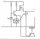
Hello Infinia. Well, I thought jimmiegin was the leader of this project? ;-D You are right. That is why I "caught him" trying to run away on an earlier post. I still would like to hold on to the 723, as I feel that a lot of constructers over the years, has used it poorly. One of the things I am remarking every time I see a circuit of a power-supply is the ommittence of a proper base-emitter resistor, at the power-pass-transistors, to take care of the Icb0 current, that is highly temperature depend, and can cause terminal runaway, if not dealt proberly with. I really like the homepage You have found in #50, but he also has forgotten that resistor. Has any of You looked deeper into the schematic, I posted with the 723, where I am using it in inverting mode, instead of the usual mode? I read no comments.
Answer to WSJ post #38: I posted to jimmiegin. Regarding a SCR pre-regulator: it is a great idea. I am just a little scared about noise. Elector Electronics made a bench power-supply, with a FET, but still switching on and off. Elektor made an other solution, where they had a transformer with a center-tap, and with 3 large diodes, and 2 thyristors, they could switch between half and full raw supply. Anybody interested?
Hi Soeren
I think of both you and WSJ are technical leads guiding the "customer" jimmiegin on what to consider for decent lab supply. LM723 is a great chip with lots of variations possible. You are the artists I don't want to over influence your style. let your expressions bloom.
I think of both you and WSJ are technical leads guiding the "customer" jimmiegin on what to consider for decent lab supply. LM723 is a great chip with lots of variations possible. You are the artists I don't want to over influence your style. let your expressions bloom.
🙂Hello Elvee.
Have You consideret using the little but dammed smart TLC431?
- a variable zenerdiode! - used in almost every SMPSU.
Soeren Poulsen Denmark
if you put hv transistors... it has no U limit
Attachments
Last edited:
Soeren, thanks for the revised version of the second schematic I originally posted. That will do fine until I have worked through the many tutorials links and pdf files on regulator design. Good luck with your power supply. After spending 16 hours a day reading on this subject for the past three days i think i may be getting it. Maybe you will post your end result somewhere and a pic, in due i will do just that. Would be very interested to see what you guys come up with. God bless all
No!- no! - no! Do not run away! I have been longing to have someone to discuss the best way to use an uA723, and I am so happy to have You and our 2 american friends with us. Do take a break in reading about this topic. I am had to do it, because I am out tomorrow to play in a band, and I have some repairs to do, but I will be back in the start of the new week. You could in the meantime fint out, what kind of powertransistors You have, and download the datasheets, to determin, if they are usable for our powersupply. jimmiegin, You have my direct adress, so You can write me directly, so I can send You a lot of examples of other bench-powersupplies. It is allways good, to see, and evaluate, how things can be done. For a couple of days: All the best, Soeren
Electronic loads are pretty cool to have around. simple one here
1) add a small PS for independent control circuitry and cooling fan so can test HV and dynamic loads for transient tests.
2) add a function generator input for dynamic loading
This is an excellent idea. A current sink can be adjusted to any current desired.
A dual set point with one current level switched on and off can be used to evaluate Load transient recovery time and loop stability.
This test is extremely important, because a change in load current can cause large voltage transients as the loop recovers from the current change. Large voltage transients on a DC power supply output can couple into the circuit it's powering and that is called NOISE.
Take a look at this Agilent Application note:
Load Transient Recovery Time
A constant voltage dc power supply is designed with a feedback loop which continuously acts to maintain the output voltage at a steady-state level. The feedback loop has a finite bandwidth, which limits the ability of the power supply to respond to a change in the load current. If the time delay between the power supply feedback loop input and output approaches a critical value at its unity gain crossover, the power supply will become unstable and oscillate.
http://cp.literature.agilent.com/litweb/pdf/5952-4190.pdf
No!- no! - no! Do not run away!
what kind of power transistors You have, and download the datasheets, to determin, if they are usable for our power supply. All the best, Soeren
I like this one, with no top you can see what you get. This a Darlington FT359, I will scan the data sheet and post it later. NPN W: 125, V: 350, A: 15, hFE, min: 250, TO3. What other parameters are you looking for....SOA?


Do you wonder "Why is my power supply too hot"?
Do data sheets lead you down a dark path of no return?
If so you may find this info interesting.
Proper Use of Thermal Derating Curves for Power Modules - Power Solutions | DigiKey Technology Zones
Do data sheets lead you down a dark path of no return?
If so you may find this info interesting.
Proper Use of Thermal Derating Curves for Power Modules - Power Solutions | DigiKey Technology Zones
- Status
- Not open for further replies.
- Home
- Amplifiers
- Power Supplies
- lm723 variable supply schematic question