I learned from Alexmm about a SMPS designed for the QUASAR and decided to open this thread since other projects may benefit from it.
The schematics can be downloaded HERE.
The first group buy is now closed, but the second one is still open HERE.
If you are interested you can register in English.
I understand from Tibi that these boards should cost around 7 Euros each plus shipping.
Please let me know if you are interested so we can consider the possibility of having boards for all US buyers sent to a single address for redistribution ($aving $hipping).
At this point this is all I know about it. Probably Tibi can help out answering questions.
Cheers!
Attachments
Last edited:
it looks interesting ..... i am interested also but also it would nice to know how many amps is provided by this psu ....if there is any other voltage abilty and a few more things regarding protection
if there is a related thread can you please point it to me ???
thanks sakis
if there is a related thread can you please point it to me ???
thanks sakis
Guys
As mentioned above, I wrote all I know about this project.
I will contact Tibi about this post and ask him to help.
Yes, it would be nice to hear from people that already assembled and tested this power supply. Since the first group buy has ended, there is probably a few people out there that can provide feedback.
Thanks!

I learned from Alexmm about a SMPS designed for the QUASAR and decided to open this thread since other projects may benefit from it.
...
dudaindc,
Many thanks for this nice introduction !
Regards,
Tibi
it really does look good, I wish there would be bottom and top copper avalieble for diy making... and price seems to be low, but shipping would kill it for you guys in US, probably not so much here in EU
We are going to share all info's but not the gerbers.
Behind PCB layout is lot of work and we prefer to benefit from this at some point in time.
")
Shipping will not be an issue if someone will redistribute the board within US.
Regards,
Tibi
it looks interesting ..... i am interested also but also it would nice to know how many amps is provided by this psu ....if there is any other voltage abilty and a few more things regarding protection
if there is a related thread can you please point it to me ???
thanks sakis
The SMPS was initially designed to power QUASAR modules.
Some people have used these SMPS for other class AB amplifiers as well, with excellent results.
In the first version of this SMPS we have added a module protection as an optional board.
We'll keep the same in the future.
As long this is not a kit, you are free to change output voltages up to your needs. So, voltage ability is up to the builder.
Related thread is here http://www.elforum.ro/viewtopic.php?f=41&t=34816
At the end of this thread you'll see many finished SMPS by various folks.
As you can see, we have started the project from a SMPS presented here on diyaudio.
During prototyping and later based on users feedback, we have performed several changes to initial schematic.
Regards,
Tibi
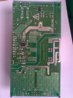
The photos don't match the schematic. (TR2/TR3 interchanged, diodes marked D104-D107 in the schematic and D7-D9 on the board).
Is the board in the photos a later revision ?
pjp,
The schematic presented on vicol-audio is latest version. Presented PCB will not match this schematic.
We are going to make several major changes on PCB layout.
The main change is to achieve a better layout grounding between SG3525; IR2110 ground and choppers ground.
Regards,
Tibi
Sounds good, if you would only find out for me, how much would be shipping to me an send me PM, that would be great, since there si nice priceThose wo are interested in this SMPS can register here (on this thread; hope is OK!) or here (where we have currently collected 24 PCB requests).
Regards,
Tibi
To explain a litlle the history of this smps.pjp,
The schematic presented on vicol-audio is latest version. Presented PCB will not match this schematic.
We are going to make several major changes on PCB layout.
The main change is to achieve a better layout grounding between SG3525; IR2110 ground and choppers ground.
Regards,
Tibi
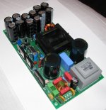
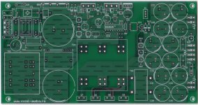
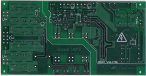
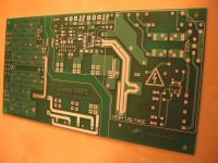
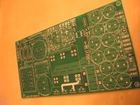
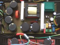
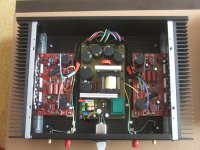
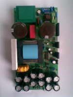
There was/will be 3 variant for now for this smps :
- version 0 = as in the first 2 pictures attached
- version 1 = as in the 2 last pictures attached
- version 2 = in the work now for future release
So , regards for all .
Attachments
and fixed mistakes too?
We had few minor pcb mistakes which have been corected and we'll release gerbers (from corrected version 1) to public domain.
We are preparing pcb version 2 which will be more flexible and probably partially monted (SMD parts).
The new board will allow tube fanatics to have a SMPS source as well.
Regards,
Tibi
- Status
- This old topic is closed. If you want to reopen this topic, contact a moderator using the "Report Post" button.
- Home
- Amplifiers
- Power Supplies
- ±50V SMPS for Quasar Amps (& others)