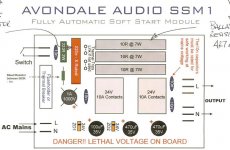
I am building a soft start module from avondale audio... however the board didnt come with part specifics and I dont knowenought about each part (well a few I do) to competenlypick them out. Could I get some help from the knowledge base here? ATtached is the board layout.
Attachments
I see.....
4x 10nF capacitors (ceramics?)
1x 220nF X rated fim capacitor
2x 470uF 35V electrolytic capacitor
1x 100uF 35V electrolytic capacitor
3x 10R 7W resistors
1x 220R 2W resistor
1x 800K-1M resistor (>1/4W?)
2x 24V zener diodes
2x 24V 10A relays
1x 1A 1000V bridge rectifier
I see there are some hand drawn notes that aren't fully visible pointing to the 220nF cap and the 10R resistors.
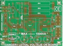
The board on Avondales website shows a MOV (metal oxide varistor) to the right of one of the 470uF caps and it has 6R8 resistors instead of 10R.
http://avondaleaudio.com/audiophile-hifi-diy/soft-start-module/
4x 10nF capacitors (ceramics?)
1x 220nF X rated fim capacitor
2x 470uF 35V electrolytic capacitor
1x 100uF 35V electrolytic capacitor
3x 10R 7W resistors
1x 220R 2W resistor
1x 800K-1M resistor (>1/4W?)
2x 24V zener diodes
2x 24V 10A relays
1x 1A 1000V bridge rectifier
I see there are some hand drawn notes that aren't fully visible pointing to the 220nF cap and the 10R resistors.
The board on Avondales website shows a MOV (metal oxide varistor) to the right of one of the 470uF caps and it has 6R8 resistors instead of 10R.
http://avondaleaudio.com/audiophile-hifi-diy/soft-start-module/
yeah the hand notes are for the large 10R resistors that states for the US version to use 4.7 Ohm instead and the other note points to the 220nf X rated cap and states "Series capacitor 1uF" ...
I am confused on what part to get for the relays... digikey gives you so many options for them I dont know where to begin...
Anything special for the bridge rectifier? and what is a x-rated cap... I think its a UL rating for flame retardation correct?
I wish they would have supplied a BOM (I asked them for one and they really wouldnt supply me with one...)
thanks for your help! what you see is all the info I got for 10GPB a board...
HaLo6 said:...
I am confused on what part to get for the relays... digikey gives you so many options for them I dont know where to begin...
Yea the relay will be the key and the hardest part here. You really need to push to get a part number for that. or go hunting for a needle in the hay,
Otherwise you need to manually measure all the pin spacings and go part hunting... reviewing various data sheets of detailed mech drawings for a match. also from data sheet determine the electrical pin locations of the normally open contact match the PCB traces.
Fact1) coil voltage is 24Vdc
Fact2) the relays normally open contact is going to be across the series of power resistors. It closes that after power is applied.
I think I might have a winner........
http://search.digikey.com/scripts/DkSearch/dksus.dll?Detail&name=255-1108-ND
http://search.digikey.com/scripts/DkSearch/dksus.dll?Detail&name=255-1108-ND
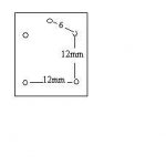
theAnonymous1 said:I think I might have a winner........
http://search.digikey.com/scripts/DkSearch/dksus.dll?Detail&name=255-1108-ND
Awesome looks that that is it, according to the datasheet its 12 & 12.2mm
So for the X-rated cap, does that mean a 1uF cap in series with the 220nF cap?
Vishay MKP X1
Once I am all done with this I'll compile the list so if anyone else want to build this module they won't have to do the leg work!
For the "Bleed Resistor" of 1M Ohm
Bleed Resistor
Vishay MKP X1
Once I am all done with this I'll compile the list so if anyone else want to build this module they won't have to do the leg work!
For the "Bleed Resistor" of 1M Ohm
Bleed Resistor
Here are the 10nf caps (C2, C3, C7, C8)
10nF Caps
And the Zener (lots of options in the selection criteria most of which I don't understand like "current reverse leakage" and "Forward Voltage" ... how exactly do those play into part selection ... I semi-understand the theory of the terms after reading "Art of Electronics" but I am missing the practical knowledge and understanding (due to my inept lack of experience") )
)
Zener
10nF Caps
And the Zener (lots of options in the selection criteria most of which I don't understand like "current reverse leakage" and "Forward Voltage" ... how exactly do those play into part selection ... I semi-understand the theory of the terms after reading "Art of Electronics" but I am missing the practical knowledge and understanding (due to my inept lack of experience
) Zener
If you created the schematic, then it is your's.
You can post your schematic.
But that defeats the copyright holders intent if they had wanted to keep the operation secret.
Morally it's wrong, but not breaking copyright law.
Comments on whether anyone disagrees please.
Would that be why some software creators have a anti-reverse engineering clause?
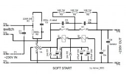
I prefer to connect the metal oxide varistor immediately after the fuse. In your diagram, I prefer to connect the varistor between "TP3" and "TP1", minimizing the length of the high current path. When a surge occurs, I want the varistor to blow the fuse immediately.
If D1 and D2 are zener diodes, perhaps you could use a different schematic symbol which emphasizes this fact.
Personally, I prefer the soft start circuit discussed in National Semiconductor's / Texas Instruments' application note AN-1849, Figure 4. Or the soft start board sold right here in the DIY Audio Store http://www.diyaudio.com/store/amplifier-circuit-boards/sssdp.html
Last edited:
- Status
- This old topic is closed. If you want to reopen this topic, contact a moderator using the "Report Post" button.
- Home
- Amplifiers
- Power Supplies
- Soft Start Module