Ok, I was aware of the heatsink needs, I had earmarked a heatsink about F5 sized....
To semi-quote some DCB1 advice, you will need F5 size sinks for ~2A. For 4A or even more to get some headroom, you will have to get into some huge aleph territory... It will depend on some other staff though like voltage drop etc... Excel should be your friend
")
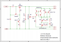
It will be the DCB1 reg schematic to implement. But with 4 leds in the CCS. That one has been used up to 3A. The dissipation is going to be Vin-Vo times full set current for the CCS Mosfets (very hot) while the dissipation for the output Mosfets is going to be Vo(12V) times (CCS-load current). Setting the CCS should be mean average at load plus peak demand and 200mA spare. Do it on air p2p like a high power valve circuit with thick copper wire connections for the rails and grounds and don't rely only on solder to hold hot stuff. Twist and screw where heat is much. Keep any electrolytic as cool as you can and use only 105C parts.
Sorry not +5.0V, but +4.7V.
My WaveIO board is running with this config. and seems to be good.
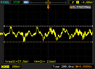
Can you take a scope picture of its output on dummy load resistor for nominal WaveIO current at 10nS/2mV div and shortest probe ground fixture possible? I want to observe something, thanks.
Lookie lookie, my first reflector powered up, and a little adjustment at the pot, it was dead on 5V, so happyThanks, Salas, off to heating up the soldering iron now
It is going to be fun to explore !!
Will swap out the Bib with this later for a comparision.Attachments
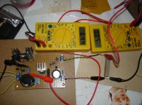
Right said Fred.Lookie lookie, my first reflector powered up, and a little adjustment at the pot, it was dead on 5V, so happy
Can you take a scope picture of its output on dummy load resistor for nominal WaveIO current at 10nS/2mV div and shortest probe ground fixture possible? I want to observe something, thanks.
OK, however would you give me a time of a few days? because my business is busy
Kazuo san,
I'm glad you've improved the reflektor. I am planning to try the new version. However, I don't have STP55NF06L at hand. Can I still use MTP3055VL as M3?
Thank you for having you be interested in this circuit
Simulation says MTP3055VL is not good, because the output impedance does not go lower sufficiently. However spice model is not real world. It may be worthy to try.
But I recommend STP55NF06L at present.
BTW some advice.
Improved Reflektor is going on experimentation, having both merits and demerits. I will plan to change some config.
Cheers
Voltage Reference - Shunt Voltage Reference - LM4040A20 - TI.com[/url]
pro/cons with passive stuff?
The noise density from LM4040 is 35uv/rms (10hz-10khz) which is already much higher than some LDO's. For instance, LT1763 has 20uv/rms from 10hz-100khz, and NS LP5900 is even at 6.5uv/rms. I am thinking about using Onsemi or Sipex TL431 as the 2.5V Vref. Those TL431s have very low noise internal Vref (around 50nv/hz @10hz - 40nv/hz @100khz).
Last edited:
You will need a 4th LED on top left so to have some margin for easier R1 values since the Vgs is going to be higher in the current region you aim at. You gonna need a 6th LED in the middle for 12V. You use red 1.9V Vf LEDS. You may skip R4 & R5. On the positive one change the connection of Q6's gate for going to ground instead of D pin. Going to D is a Mez DCB1 specific trick only. For circa 4.3A CCS you gonna need 0.56R R1 (ballpark). That resistor is gonna dissipate ~10W(!) so use a sinkable one. Maybe a Caddock.
Niko I have added a 47uF cap at the output of the BiB right on the Shigaclone PCB entrance and noise has dropped to about 10mV

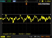
But hitting auto gives me this...
It is not detectable with shigaclone off
Can you please advise? Do I have to worry about this?
C103 is FR at 47uF, R107 is 0R47 and cap at the power entry point is FR 47uF
Thanks again
But hitting auto gives me this...
It is not detectable with shigaclone off
Can you please advise? Do I have to worry about this?
C103 is FR at 47uF, R107 is 0R47 and cap at the power entry point is FR 47uF
Thanks again
Attachments
Last edited:
- Status
- This old topic is closed. If you want to reopen this topic, contact a moderator using the "Report Post" button.
- Home
- Amplifiers
- Power Supplies
- The simplistic Salas low voltage shunt regulator