http://sound.westhost.com/project15.htm
What number does he mean at the bottom? First he says to use 10mF, then he says not to use more than 0.47mF.
Increasing the capacitance (especially at the input) is recommended, and I would suggest 10,000uF as the ideal instead of the 4700uF shown. This will reduce hum even further, and provide greater stability against short term mains voltage changes. Increased output capacitance will help when powering Class-AB amplifiers, to account for their sudden current demands. I do not recommend more than 4,700uF, as the charging current will be very high.
What number does he mean at the bottom? First he says to use 10mF, then he says not to use more than 0.47mF.
Hi
He is saying use min 10,000uF before the transistors and not to use more than 4700uF after the transistors.
If u use more than 4700uF after the trans. it would draw too much current during start up and may blow the serise transistor, which actually reduces the ripple.
rgds
Sumit
He is saying use min 10,000uF before the transistors and not to use more than 4700uF after the transistors.
If u use more than 4700uF after the trans. it would draw too much current during start up and may blow the serise transistor, which actually reduces the ripple.
rgds
Sumit
Rod Elliot's Capacitance multiplier
Good day Sir,
I actually used 10,000uF after the transistors but it didn't fry the TO218 transistors that I suspect counterfeits from China (TIP2955/TIP3055), I also implement capacitance multiplier ps in all my SS/chip amp projects, as it surpass the benefits versus the costs. If I needed regulated ps, i connected it after the capacitance multiplier. The diffrence between the linear can clearly be observed.
Regards,
Efren")
Good day Sir,
I actually used 10,000uF after the transistors but it didn't fry the TO218 transistors that I suspect counterfeits from China (TIP2955/TIP3055), I also implement capacitance multiplier ps in all my SS/chip amp projects, as it surpass the benefits versus the costs. If I needed regulated ps, i connected it after the capacitance multiplier. The diffrence between the linear can clearly be observed.
Regards,
Efren
" I actually used 10,000uF after the transistors but it didn't fry the TO218 transistors that I suspect counterfeits from China (TIP2955/TIP3055) " Using any semiconductor device near its maximum rating is not adviceable and would result in reduction of life of the device. The transistor may not blow as the surge current capability of the device is high, but still, charging a fully discharged 10000uF capacitor causes the device to over conduct its limit, and would cause life reduction. A lot of times what saves the transistor is the impedance of the transformer which limits the output current.
" Would a TIP33C/TIP34C (100V 10A) instead of a TIP2955/TIP3055 (100V 15A) work for a Capacitance Multiplier transistor " Its all about safety margin. If upto 4 to 5 amp contineous is required TIP33/34 can be used.
rgds
Sumit
" Would a TIP33C/TIP34C (100V 10A) instead of a TIP2955/TIP3055 (100V 15A) work for a Capacitance Multiplier transistor " Its all about safety margin. If upto 4 to 5 amp contineous is required TIP33/34 can be used.
rgds
Sumit
The amp(s) I'd like to use this supply for will probably need to output a peak current of about 25 A. Will I be OK with the number of caps shown, or do I need to parallel?
The input caps and input filter caps that I would like to use are rated at 4.4 A and 2.3 A ripple current, respectively.
The input caps and input filter caps that I would like to use are rated at 4.4 A and 2.3 A ripple current, respectively.
25amps peak :- which transistors r u using?
This supply is ment for class A operation not for AB or B type amps. What kind of amp u r planning?
You probably need to parallel caps but u need a transiator hefty enough to handle the in rush current. May be u need to parallel transistors too.......
This supply is ment for class A operation not for AB or B type amps. What kind of amp u r planning?
You probably need to parallel caps but u need a transiator hefty enough to handle the in rush current. May be u need to parallel transistors too.......
two channels of lm3886 running on +-35Vdc into 8ohm speaker can demand transients approaching 22Apk.454Casull said:A 10-channel LM3886-based amp. I don't know which transistors I will be needing yet.
What will 10 channels demand?
I only want 330W peak out of it. Adding up all the calculated currents per channel, I'm at about 20 A, with a few more for good measure.AndrewT said:two channels of lm3886 running on +-35Vdc into 8ohm speaker can demand transients approaching 22Apk.
What will 10 channels demand?
The (slightly old, but about the same) calculations I'm using can be found here:
http://www.audiocircle.com/circles/index.php?topic=67252.msg622618#msg622618
10 channel active system with different impedance loading on each channel and different power delivery on each channel.AndrewT said:two channels of lm3886 running on +-35Vdc into 8ohm speaker can demand transients approaching 22Apk.
What will 10 channels demand?
I have no idea how to model the peak current demand.
You can't simply add up the current for each channel?AndrewT said:10 channel active system with different impedance loading on each channel and different power delivery on each channel.
I have no idea how to model the peak current demand.
That's why I said that.AndrewT said:I have no idea how to model the peak current demand.
What's wrong with taking it from I=P/R given R is the minimum impedance and P is the power for the whole driver? That should be fine for a full-power single tone at the minimum impedance, which would never even happen with music.AndrewT said:That's why I said that.
That's what I did in the spreadsheet, btw. If you could have a look at that and tell me if my calculations are off, that'd be great.
EDIT: Latest revision here
http://www.sendspace.com/file/7dmtb7
which transistor to use?
Hello .454Casul
try this for size, perhaps it will give you enough headroom:
MJ14002- npn, 300w,80v, 60A (TO-3)
MJ14003-pnp, 300w, 80v, 60A (TO-3)
MJ11032-npn, 300w, 120v, 50A, darlington, (TO-3)
MJ11033-pnp, 300w, 120v, 50A, darlington, (TO-3)
just check if such devices are available in your area, i got those specs from Electronics Enthusiast, Projects & Circuits vol.5, locally available in our country.
best regards,
efren.
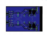
branet,
it looks as if you've done this so many times, nicely done but the clamping diodes at the output seems to be missing, unless you intend to solder them directly on the foil side.,
in my limited knowledge, clamping diodes will protect the power transistors in the event that those filter capacitors (before the transistors, after the rectifiers) discharges faster than those in the output which rarely happens...
just to be sure better to have them.
will these be for class A amp? (a MUST for all class A amp, unless you'll be using lead-acid batteries).
Best Regards
it looks as if you've done this so many times, nicely done
but the clamping diodes at the output seems to be missing, unless you intend to solder them directly on the foil side., in my limited knowledge, clamping diodes will protect the power transistors in the event that those filter capacitors (before the transistors, after the rectifiers) discharges faster than those in the output which rarely happens...
just to be sure better to have them.
will these be for class A amp? (a MUST for all class A amp, unless you'll be using lead-acid batteries
).Best Regards
- Status
- This old topic is closed. If you want to reopen this topic, contact a moderator using the "Report Post" button.
- Home
- Amplifiers
- Power Supplies
- Rod Elliott's capacitance multiplier supply