Hi Alex,
Totally understood that RTP3 is a balance circuit and SVP is single-ended.
I did compare FVP5A to RTP3C. LOL, I just hope I could get some tip from you so that I can derive the SVP-2 from the RTP3D circuit
Sorry for the off-topic. Feel free to email me via the forum if you want to explore SVP-2.
Thanks!!
")
Fred,
My understanding is that the SVP2 circuit is essentially the same as the FVP5a that I posted. Allen himself said that the SVP1 is the same as the FVP5a, and the VSE publicity material states that the SVP2 is basically and SVP1 with an extra line input - the active circuits are almost identical. There is no way that you could "derive" the SVP2 from the RTP3.
Alex
Problem with SSHV2?
I'm hoping to use the SSHV2 regulator board to give me 300vdc out at 35-50mA. This is a purchase from the group buy of the board and parts kit.
Today I put together a PS source for it. PS is a 560vct transformer full-wave rectified using UF4007 diodes into a 50uF cap, which yields me about 395v. That's too much, so I made it a pi filter with a 1k resistor and another 50uF cap to drop about 50v at my expected max of 50mA current. This is just for testing and breadboarding purposes. I intend to get a more suitable transformer for my final build.
So right now I've measured about 350-360vDC coming into the SSHV2 board. I'm using two 3.3k/10w wirewound resistors in series (6.6k on the output) which should yield 45mA at my 300v target, which I thought was decent for testing.
After lots of prep, I hooked it up and gave it a brief test. Incoming voltage was around 360v, and current using the test points was 24mA with an output of just a bit under 200v. I adjusted the current to about 35mA (via R4) but I can't adjust R11 to get more than about 220v MAX. Note that all components and heat sinks seem to be quite cool (but my tests were all pretty short, most under a minute in length).
Any ideas what is going on? I'm dropping 160v +/- in the regulator at 24-35mA current, suggesting there's 4.5k to 6.6k of resistance in the regulator. I'm burning in the vicinity of 4-6W in the regulator. It's remaining cool.
I'm puzzled and now getting beyond my ability to troubleshoot this. I'd certainly appreciate help. Thanks.
I've had a problem with my SSHV2 and posted a question about it here. Not sure where is the best place to post it, so I'm posting a link here in case I should have posted my question here. Perhaps keep the discussion on the other thread for consistency and clarity's sake though.
Thanks for any input.
Carl
Thanks for any input.
Carl
I suggest you split the regulator into two sections.
The CCS section and the Voltage regulator section.
Add a resistor load to the CCS. try 50mA and 10Vdc, i.e. ~200r. It will dissipate ½W if and when it gets up to the 50mA
Apply a low DC voltage to the CCS section. I suggest you start at 5V and wind up to 15V.
increase the DC voltage slowly and measure what current is flowing from the DC supply and through the dummy load, at each voltage change.
This is a low voltage way of proving the CCS part up to the maximum current you require.
Once you have this running report back.
Post a pic and the CCS sch.
I have previously stated this testing philosophy in your regulator Threads.That's good advice for safe testing the current source and its setting.................
It seems that you and the other Members can't be bothered reading.
Salas,
the splitting of the Salas Style Shunt Regulators is a very powerful technique for trouble shooting.
Would you consider adding a link in post 1 of each Thread explaining the test process?
The technique can also be used during assembly, by just building up the CCS components and testing this first part on a low supply voltage before starting the voltage regulator section. This is especially useful for the HV regulator in that it avoids the need to build an HV supply to first test the assembly.
Last edited:
Thanks, AndrewT for the idea and Salas for moving my thread. Can this be done without breaking traces (it's the pcb from the TeaBag group-buy). I don't recall any obvious point to split this, but I'll have a look. Maybe I can de-solder a resistor or two...
I've had another suggestion to unload the output, set the current, then the voltage, then load the output, reset the current, then reset the voltage. I'll try that first since it seems easier.
I've had another suggestion to unload the output, set the current, then the voltage, then load the output, reset the current, then reset the voltage. I'll try that first since it seems easier.
Surely they should be connected for the Kelvin circuit to close circuit. BTW when loading it with a dummy to simulate a target load, remember, the calculation is not about exhausting the CCS setting but the expected consumption. You set the CCS +20mA above expected load. That's for HV pre-test to set both CCS and Vout as in the guide.
As for R5 10R T.P. it will drive the set CCS current to its end node anyway even when fed from LV. That is the rail line ending to F+. So you don't need split pcb tracks anything. All you have to do is short F+ to F0 closing circuit to the LV source, be it a 9V battery even. Leave S+ S0 alone. Don't do that test with HV tension.
As for R5 10R T.P. it will drive the set CCS current to its end node anyway even when fed from LV. That is the rail line ending to F+. So you don't need split pcb tracks anything. All you have to do is short F+ to F0 closing circuit to the LV source, be it a 9V battery even. Leave S+ S0 alone. Don't do that test with HV tension.
OK, looking at the schematic I can now see that the F point is directly tied to the CCS, and disconnected should isolate it for the most part. And how low v would be important. There's a lot going on in the circuit I just don't understand (transistors don't always make sense to me) so I appreciate your patience.
Tonight based on the suggestion of a knowledgeable friend (knows and has used the SSHV2) I tried tying F+ to S+ and F0 to S0 but no load attached (only load should be the regulator). He suggested setting the CCS to 20mA (for the regulator) then setting output voltage to 300v. Then attaching the real load and adjusting CCS such that 300v at the output, then adding 20mA for the regulator.
When I did this, the test points were showing 0.030v, or 3mA and I couldn't adjust that at all. The output was reading 393v (reflecting my PS raw output minus small losses at 3mA, I assume). Next I'll try tying F+ to F0 and leaving S terminals open, then powering with a 9v battery to check the CCS. Note R4 was adjusting the current fine when I had a load attached. At this point I'm wondering if something may be wrong with the regulator since I understand it should pull 20mA just to operate. I'll also check solder joints and wiring on the board when I work on it tomorrow.
Carl
Just ran a check over lunch break using a 9v battery and 235R on the output with S+ and S0 disconnected (isolating the CCS). I can't vary the current at all or at most a very tiny amount (maybe a few tenths of milliamps). Voltage dropped by this resistor was about 0.5v.
So can I assume it's the CCS (or maybe both ). I'll look at the solder joints, look for cross-connections, etc. I've had difficulty with the DN2540 in CCS before. Seems it may be a bit fragile. I don't think I used a ground strap when handling them.
Thanks for any additional input!
So can I assume it's the CCS (or maybe both
). I'll look at the solder joints, look for cross-connections, etc. I've had difficulty with the DN2540 in CCS before. Seems it may be a bit fragile. I don't think I used a ground strap when handling them.Thanks for any additional input!
Last edited:
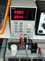
I had a broken input section SSHV2 around so I fixed it and measured it to show you. After I replaced both 2540s and removed the two associated Zeners, I tied F+ & F0 together (the output connector's far left and right points). Nothing else wired or loaded output wise. Firing it up and adjusting the CCS (TP) trimmer for 45mA at 9V in from a cheap lab PSU, the current draw climbed only by 5mA when at 20V without any dummy. TP checks with DVM were +/-1mA agreeing to the PSU's output current indication. It was drawing in the 150-250mA on 6-9 LV before, no matter the trimmer set.
You look for 1.5-2V VGS across each healthy DN2540 (outer pins) when the CCS is LV powered. The damaged D5, D6 Zeners were measuring like leaky diodes. The damaged MOSFETS either showing shorted or like two diodes in series before I chucked them in the dustbin. No visual clues beyond a tiny dimple on the plastic face of the shorted MOSFET. Near its drain pin.
Q1 was loose on its sink as I saw and some over-current incidents had taken place during a tube phono build I was told. Still nothing was visually smoked. So do that, just short ends like I showed and retry, checking VGS too. When power is off, confirm that the trimmer is changing value in Ohm when turned. Its absolutely safe with LV to handle and no sink for the output MOSFET is needed as no current goes to the shunt section when this way tested.
Attachments
Thanks, Salas. I had done the check with F pins tied together but didn't report. It was essentially the same as with them loaded with 235R.
But...tonight I re-did the test with a battery showing 9.04v unloaded (7.7v when attached). This time I got adjustment at the TPs from 0.172v to 1.01v or so. That actually sounds right. VGS on Q2 was just a tad over 2v (I couldn't reach the other without worrying about shorting something. I don't know why it wasn't working that way earlier, but it (the CCS at least) now seems OK.
But...tonight I re-did the test with a battery showing 9.04v unloaded (7.7v when attached). This time I got adjustment at the TPs from 0.172v to 1.01v or so. That actually sounds right. VGS on Q2 was just a tad over 2v (I couldn't reach the other without worrying about shorting something. I don't know why it wasn't working that way earlier, but it (the CCS at least) now seems OK.
- Home
- Amplifiers
- Power Supplies
- Simplistic MosFET HV Shunt Regs