Hello guys, 
I`m tried to design some simple to use & understand tool, that will be helpful for pepole that new to SMPS design. Result of my work is Exel worksheet that able to calculate some data for pulse transformer, MOSFET`s, rectifers etc. I`m planing to add suport for output filters .
To use my calculator simple plase your data to white colored graphs, & results will be calculated automaticaly.
Please consider that it`s not final version, so chek for updates.
 Don`t forget to chek the results by conventional way for the first time of using this tool.
Of course I`m very wating for your comments, critics, suggestions that will be helpful to improove the final version
Cheers ,
Anatoli Panchenko
I`m tried to design some simple to use & understand tool, that will be helpful for pepole that new to SMPS design. Result of my work is Exel worksheet that able to calculate some data for pulse transformer, MOSFET`s, rectifers etc. I`m planing to add suport for output filters .
To use my calculator simple plase your data to white colored graphs, & results will be calculated automaticaly.
Please consider that it`s not final version, so chek for updates.
Don`t forget to chek the results by conventional way for the first time of using this tool.Of course I`m very wating for your comments, critics, suggestions that will be helpful to improove the final version
Cheers ,
Anatoli Panchenko
Attachments
Ok here is some instructions...
Later I`ll place better version of it (may be this weekend)
All that you need - to search yours component`s datasheets for the needed information.
You will need datasheets for your core, MOSFET`s , driver IC, rectifer diodes. I used the same discriptions for all values and data like commonly used in components datasheets.
This project is based on calculation of SMPS from here:
http://www.national.com/appinfo/power/files/LM5030_Push-Pull-12V-60W-2001i-new-4.pdf not a lot discriptions, but look on the source - it writed on much better english then my.
Some suggestions how to begin:
1. F SWITCH Hz - select your switching frequency. Don`t go to values higher than 50000-75000 Hz for yor firs project. You will be need to create extreme good topology for your PCB, to fight against a lot of thermal & EMI losses , and other parasitic effects.
Take some expirience first.
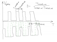
2. D MAX % - maximum duty cycle for single positive OR negative period. Its equal to MOSFET on time / MOSFET off time during one half period (phase) Also look to picture below. Good idea to select
beetwen 30-43. Look the driver IC datasheet to determinate how to set up this parameter. For example : to set up D MAX for SG3525 , you will be need to place resistor beetween pins 5&7.
3. J A/MM2 - current destiny in wires. Avoid to use values higher than 5-6 A/mm^2 without good active cooling of your SMPS, or if your SMPS
will work at high ambinet temperature. Better to increase wire area for all windings.
4. K FiLLIG OF WINDOW* or winding factor. Showing witch part of window area ( bobbin area ) are taken by COPPER (clear area of conductors, without insulation (enamel coating)) Also see link above from page 8
Good to start with 0.3...0.4 , and avoid to go to more than 0.95 -
will be difficult to wind the last turns, also avoid to go to less than
0.15... 0.2 - coupling beetwen primery to secondary windings will be bad, + losses and EMI of magnetic leakage will be high.
DO NOT FORGET TO COPY VALUE OF EXACTLY CALCULATED Kfill EX* ( K4 field) to K FiLLIG OF WINDOW* after you placed all you data about trafo. , MOSFET`s & diodes. You will recive proper value for P MAX W (power that you transformer is able to deliver) after this step ONLY.
Good lark in your future projects. And don`t waste to ask your questions.
Later I`ll place better version of it (may be this weekend)
All that you need - to search yours component`s datasheets for the needed information.
You will need datasheets for your core, MOSFET`s , driver IC, rectifer diodes. I used the same discriptions for all values and data like commonly used in components datasheets.
This project is based on calculation of SMPS from here:
http://www.national.com/appinfo/power/files/LM5030_Push-Pull-12V-60W-2001i-new-4.pdf not a lot discriptions, but look on the source - it writed on much better english then my.
Some suggestions how to begin:
1. F SWITCH Hz - select your switching frequency. Don`t go to values higher than 50000-75000 Hz for yor firs project. You will be need to create extreme good topology for your PCB, to fight against a lot of thermal & EMI losses , and other parasitic effects.
Take some expirience first.
2. D MAX % - maximum duty cycle for single positive OR negative period. Its equal to MOSFET on time / MOSFET off time during one half period (phase) Also look to picture below. Good idea to select
beetwen 30-43. Look the driver IC datasheet to determinate how to set up this parameter. For example : to set up D MAX for SG3525 , you will be need to place resistor beetween pins 5&7.
3. J A/MM2 - current destiny in wires. Avoid to use values higher than 5-6 A/mm^2 without good active cooling of your SMPS, or if your SMPS
will work at high ambinet temperature. Better to increase wire area for all windings.
4. K FiLLIG OF WINDOW* or winding factor. Showing witch part of window area ( bobbin area ) are taken by COPPER (clear area of conductors, without insulation (enamel coating)) Also see link above from page 8
Good to start with 0.3...0.4 , and avoid to go to more than 0.95 -
will be difficult to wind the last turns, also avoid to go to less than
0.15... 0.2 - coupling beetwen primery to secondary windings will be bad, + losses and EMI of magnetic leakage will be high.
DO NOT FORGET TO COPY VALUE OF EXACTLY CALCULATED Kfill EX* ( K4 field) to K FiLLIG OF WINDOW* after you placed all you data about trafo. , MOSFET`s & diodes. You will recive proper value for P MAX W (power that you transformer is able to deliver) after this step ONLY.
Good lark in your future projects. And don`t waste to ask your questions.
Attachments
- Status
- This old topic is closed. If you want to reopen this topic, contact a moderator using the "Report Post" button.