I have a uFonken flat-pak sitting here, waiting for a few things, but I'm trying to figure out the best glue-up sequence while I wait.
I can see a few ways of doing it but can't seem to find that one way that makes the most sense WRT when/how to fit the brace and close it up.
Any tips?
I can see a few ways of doing it but can't seem to find that one way that makes the most sense WRT when/how to fit the brace and close it up.
Any tips?
I thought at one time I forwarded a set of photos of mock assembly for one of these kits to Dave, but I'll try to replay in the theatre of my mind
always dangerous, that") ( build enough of a range of enclosures and muscle memory takes over - it's a chore to actually think about how to describe it )
( build enough of a range of enclosures and muscle memory takes over - it's a chore to actually think about how to describe it )
As I don't know how far you've proceeded, I'll start from the beginning. The micro is a small box, so even if you have more than all the clamps you need, one of the issues you'll encounter is having enough room to fit more than a few at each glue up step. Of course, if you're using a brad nailer, your waiting time between steps is significantly reduced.
There's no magic, "right" sequence, but I like to go as follows, checking for squareness at each step:
- top, back & bottom,
- port shelf, spacer blocks and front (port spacer blocks should run all the way to the back panel, and might finish slightly proud of the front panel - you can sand flush later)
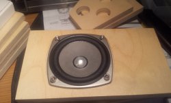
- driver brace - while these are cut for a light contact on a dry fit assembly, you'll want to test fit and adjust during your build. Install the driver first- the front of brace should have a light interference fit - it's better to have a slight gap than be too tight, and if the latter, sand down the contact surface of the brace. If too loose, add a light shim of paperboard, or foam tape.
- remove driver and install brace slightly below driver's center
- use sanding block to ensure the layers comprising the bottom and port are even with front and back
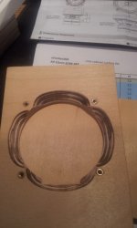
- line with felt - this enclosure is way too tiny for internal access after fully assembled, so measure and mark boundaries of lining on second side and affix before attaching to enclosure
I don't think I've missed anything?
always dangerous, that
( build enough of a range of enclosures and muscle memory takes over - it's a chore to actually think about how to describe it ) As I don't know how far you've proceeded, I'll start from the beginning. The micro is a small box, so even if you have more than all the clamps you need, one of the issues you'll encounter is having enough room to fit more than a few at each glue up step. Of course, if you're using a brad nailer, your waiting time between steps is significantly reduced.
There's no magic, "right" sequence, but I like to go as follows, checking for squareness at each step:
- top, back & bottom,
- port shelf, spacer blocks and front (port spacer blocks should run all the way to the back panel, and might finish slightly proud of the front panel - you can sand flush later)
- driver brace - while these are cut for a light contact on a dry fit assembly, you'll want to test fit and adjust during your build. Install the driver first- the front of brace should have a light interference fit - it's better to have a slight gap than be too tight, and if the latter, sand down the contact surface of the brace. If too loose, add a light shim of paperboard, or foam tape.
- remove driver and install brace slightly below driver's center
- use sanding block to ensure the layers comprising the bottom and port are even with front and back
- line with felt - this enclosure is way too tiny for internal access after fully assembled, so measure and mark boundaries of lining on second side and affix before attaching to enclosure
I don't think I've missed anything?
Thanx Chris.
We haven't done a build sequence for the micros, but the milli is very similar, here is a mock assembly of one of those that might be helpful.
http://p10hifi.net/FAL/downloads/milliSize-FP-assembly.pdf
dave
We haven't done a build sequence for the micros, but the milli is very similar, here is a mock assembly of one of those that might be helpful.
http://p10hifi.net/FAL/downloads/milliSize-FP-assembly.pdf
dave
- remove driver and install brace slightly below driver's center
(I believe you, but I'll mention the plans show the brace centered)
Can you elaborate on this a little bit? How much is slightly? The width of the brace? 1/2 the width of the brace, maybe?
And from what you wrote it seems like any contact with the driver is enough contact between the brace and driver. No need to shoot for some 'perfect' amount of contact.
Last edited:
- remove driver and install brace slightly below driver's center
(I believe you, but I'll mention the plans show the brace centered)
In the millis & micros that sport a horizontal brace it can be centred on the driver as that places it well above the centre of the back.
In the boxes with a vertical brace, it is placed off-centre of the back. Since the drivers are centred on the front baffle, the holey brace ends up off-centre on the driver as well.
dave
Well I guess I goofed that up. I moved the brace slightly off center but moved it toward the center of the box. But only by about 5mm so it's not making much of a difference as far as being centered. Some slavish attachment to symmetry I guess. And wanted that bit extra space for gluing in the lining.Thanks Dave - I really appreciate the work that has been done to make these plans available.
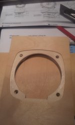
Last question (!) if I may: To recess the driver I'm making a routing template for a 1/4" router to make the 2mm recess and using captive nuts on the inside,
There are three distinct operations on the driver mount - the 71/73mm cutout, the 45 degree bevel and the 2mm recess to make the driver flush.
Is there a recommended or suggested order for these?
Thanks again
Is there a recommended or suggested order for these?
Not a question for me … i am not allowed to build anymore (except an occasional flat-oak). Chris & Bernie do that.
dave
There are three distinct operations on the driver mount - the 71/73mm cutout, the 45 degree bevel and the 2mm recess to make the driver flush.
Is there a recommended or suggested order for these?
If using a circle jig, cut driver rebate first, then driver cut-out, then flip piece and cut bevel.
If you're not lucky enough to have access to a CNC, sippy's approach makes most sense.
Make sure to allow a slight tolerance for "loose fit" on the rebate - I use about .5mm diameter - too deadly tight a fit can make rotating driver for alignment with mounting screw holes, or removing the driver for whatever reason very difficult.
I really like the supplied screws - AFAIC they're as secure as any of the types of captive nuts I've encountered so far, particularly for smaller drivers with narrow flange margins. Follow Mark's recommendation of pre-drilling and"tapping" the screws before installing, and don't over-torque the mounting screws.
Last edited:
oops - I must have Alpair on the brain - but I hear there's a pill for that
While it's become somewhat of a signature of our builds for aesthetics, and easy to achieve once you have the CNC programs written, I suspect that the trouble to rebate thin / tapered flange drivers such as most of the Fostex FE and FF series, the Mark Audio CHN70, and likely numerous TB drivers for flush mounting is likely not audible or measurable.
Thicker framed drivers with very wide dispersion, tweeters, etc, a different story methinks.
oops - I must have Alpair on the brain - but I hear there's a pill for that
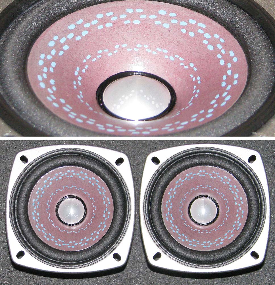
Spots are the give-away
FF85 can have spots too…
Bernie built a set of uFonken for his youngest daughter with these out of the solid mahogany i recovered from a bookcase my parents had that i made in shopin Grade 9 (ie 46 years ago)
dave
An externally hosted image should be here but it was not working when we last tested it.
Bernie built a set of uFonken for his youngest daughter with these out of the solid mahogany i recovered from a bookcase my parents had that i made in shopin Grade 9 (ie 46 years ago)
dave
Thanks for the input - I'm rebating as much for aesthetic reasons as acoustic ones - am using allen cap-bolts for retention. The rebates and ports will be matt-black and the cases veneered using Decoflex in maple or walnut.
I don't have CNC so will make up some templates that sit tightly over the front panel to ease repeatability as I suspect that once the offspring see the results they too will want a set.
Also, my plan is to make a WiFi set of these for the kitchen - not sure of the approach yet (early days) but I'm an EE so technically it shouldn't be too hard.
This is all going well - and will be finished in a few days.
Little question - how deep a rebate to cut in the front panel for the driver?
I've tried 2mm but that just isn't enough to make it touch the brace...
What do you recommend - using a deeper rebate or some thin packing foam stuck to the brace (or driver)?
Cheers!
Little question - how deep a rebate to cut in the front panel for the driver?
I've tried 2mm but that just isn't enough to make it touch the brace...
What do you recommend - using a deeper rebate or some thin packing foam stuck to the brace (or driver)?
Cheers!
Attachments
- Status
- This old topic is closed. If you want to reopen this topic, contact a moderator using the "Report Post" button.
- Home
- More Vendors...
- Planet 10 hifi
- ufonken build assembly suggestions