Hi
Over the years I have read Siegfried’s excellent material several times eg www.linkwitzlab.com/rooms.htm.
After several years of planning and saving etc, a room (6.7 * 5.3 * 2.6 m, 22 * 17 * 9 feet) mostly for music, is now available.
I am now planning to use some great drivers that I already have to build a higher output (HE drivers off tube amps) semi active dipole system.
With highish ceilings and a fair degree of human & animal floor traffic, I’d prefer to suspend the baffle off the ceiling. With generous space, I want to:
1. Minimize loss of efficiency
2. Minimize EQ
3. have a simple & cost effective baffle structure.
Material aside, the simplest way to build a large baffle, with WAF, especially off a high ceiling: is a *single transparent baffle.
Transparent dipole baffles www.diyaudio.com/forums/showthread.php?s=&postid=343896&highlight=#post343896 where Nuuk commented:
When I designed my open baffles, I had some reservations about using perspex or other plastics. Apart from the possibility of colouring through aging/exposure to ultra-violet light, there is a real possibility of scratching them.
And there is the cost of course! In the end I went for glass”
If a single large baffle (for discussion in principle, say 10 feet wide * 2 feet high, circa 3 * 0.6 m) were used for dipoles: how would this perform compared to two separate baffles of similar total area?
Thanks
Richard
Part of the answer to your question depends on the specifics of your proposed installation and the frequencies that the driver(s) in the baffle will be covering.
Part of what is likely to happen with a single large baffle (for two channels) is there will be two waves traveling into a collision across the front and back of the baffle. What happens when they hit each other will be the main question and will be related to the frequency.
If the two baffles are separate, there may be an effective discontinuity depending on the distance between the two baffles.
The second issue in the single baffle will be the sound that travels through the material and sums or cancels... usually the speed of sound through materials is higher than the speed through air. This may or may not be important.
Also the 2 foot dimension will play a big role compared to the 10 foot dimension with respect to sound within the mid bass...
Take a look at the IEC baffle response for some clues here...
_-_-bear
Hi Bear
The context:
I am looking at this right now, as a builder is very soon to build two small storage lofts in this room, and I want to make sure these do not impinge on enough space for the dipoles.
The ceiling height now is 12.5 feet (3.8 m), and the lofts as currently planned would reduce the ceiling height to 9 feet or 2.6 m.
To experiment initially I will use an adjustable electronic crossover. I will use the Phoenix woofers that i have.
The dipole “add on” to the Phoenix woofers would be likely two drivers:
- midbass (say 80 – 400 Hz) with high Vd 98 dB Lambda TD15M’s
- say 400 – 2000 Hz with 98 dB PHLs.
(Driven by a 12 watt 845 SE amp).
So my question concerns from about 1800– 80 Hz, ie wavelengths of about 0.6 - 14 feet (0.2 – 4.3 m)
Does that make it any easier to predict?
Thanks
I think filtering can overcome any problem here, though it's hard to predict the results as interaction with sound and anti-sound is very much dependent on reflected waves in the room as well.
Therefore I think placement may be even more critical than the differnces between the two baffles. I think some lower frequencies might be a bit increased in your example, but that-again-will probably be easy to solve with the filter.
My dipole experience is limited to midbass and high frequency electrostatic speakers though, where changes in placing of only centimeters can make a large difference and such intense filtering is not necessary...
If the dipole is for bass, why not use an IB set up? or quasi IB?
That assures you of excellent LF extension and avoids almost all of the other problems associated with bass and dipoles...
My feeling is that EQ will almost certainly not solve many of the peak and valley issues likely to occur with a narrow and long baffle... in the LF...
Above 80Hz, ur probably going to be ok, but pay attention to the transitions from the baffle to free space, as the freqs go up so does the diffraction... and you can use the typical "baffle step" calculators on the web to see where the dimensions will have an effect...
_-_-bear
maybe the room acoustics can help getting more bass, but eq-ing (filtering) will be necessary anyway...
Here's how you can keep it simple and affordable:
http://www.t-linespeakers.org/tech/filters/passiveHLxo.html
Here's how you can keep it simple and affordable:
http://www.t-linespeakers.org/tech/filters/passiveHLxo.html
To make the 80-1800 range with little EQ you don't need a room-width sized baffle. My shallow U-frame baffles are 48" high, 24" wide and 7" deep, and true rolloff starts at ca. 100-120 Hz (don't forget that from 200 to 100 Hz you gain ca. 6 dB from floor boundary effect). You could make two tall perspex panels with a thick wooden frame around them for stability (flexing) in the 30" x 60" range and you'd be covered to be almost dipole EQ-free. Driver low Q EQ might still be needed though. Also beware that you don't plan to position the speakers too close to the rear wall - IME 4 feet is the minimum to get an airy sound.
Hi guys
> an IB set up? or quasi IB?
as in, in a roof space? Alas it’s a cathedral ceiling – no adjacent enclosed space . .
> shallow U-frame baffles
Do you have a drawing or pic?
> from 200 to 100 Hz you gain c. 6 dB from floor boundary effect)
~ again, to leave the floor uncluttered, mine will be suspended from a cathedral ceiling, so no floor boundary gain
BTW, boundary gain, and with his final update at the end of the article, driver Qts is done very scientifically by Martin King here: www.quarter-wave.com/Project07/Project07.html
I wish it were in Excel
> You could make two tall perspex panels with a thick wooden frame around them for stability (flexing) in the 30" x 60" range and you'd be covered to be almost dipole EQ-free.
That’s basically my aim. Just need to get the maths right!
> Driver low Q EQ might still be needed though.
As proven Martin in www.quarter-wave.com/Project07/Project07.html, low Q drivers need EQ.
FYI I want to use these two drivers I have, - see attach.
Attachments
Hi,
the floor boundary gain should come in roughly when the distance to the floor is less than 1/2 wavelengths, regardless of whether they are standing on the floor or suspended. If you suspend the bass drivers high in the air, the effect will be shifted towards lower frequencies.
The low Q EQ is relatively easy to calculate and achieve - either using Linkwitz transform, or for very low Q drivers, using a shelving lowpass (as for the dipole EQ). JohnK had a post very recently on one of the forum pages how to calculatue just that, if you do a search.
For the baffle dimensions needed (excluding Q effects) there is
Linkwitz Lab
with the relevant formulas under "design models". For a simulation program there is
The Edge
which should give you a good approximation of what's needed. Final response of course should be measured on a test baffle.
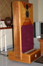
And finally, a pic of my baffles:
the floor boundary gain should come in roughly when the distance to the floor is less than 1/2 wavelengths, regardless of whether they are standing on the floor or suspended. If you suspend the bass drivers high in the air, the effect will be shifted towards lower frequencies.
The low Q EQ is relatively easy to calculate and achieve - either using Linkwitz transform, or for very low Q drivers, using a shelving lowpass (as for the dipole EQ). JohnK had a post very recently on one of the forum pages how to calculatue just that, if you do a search.
For the baffle dimensions needed (excluding Q effects) there is
Linkwitz Lab
with the relevant formulas under "design models". For a simulation program there is
The Edge
which should give you a good approximation of what's needed. Final response of course should be measured on a test baffle.
And finally, a pic of my baffles:
Attachments
Hi MBK
> floor boundary gain should come in roughly when the distance to the floor is less than 1/2 wavelengths
. . that’s centre of driver to floor?
If eg 1/2 wavelength is at 40 Hz, is the gain:
· only at that Hz
· from that Hz down
· that Hz +/ - ?
Was that in SL’s material?
Your baffles - nice finish ~
What is your dipole bass driver, EQ & Hz range?
Which software do you like?
Cheers
Hi Rick,
the frequency is a rough rule of thumb. SL actually mentions 200 to 100 Hz as the transition zone for the 6 dB gain based on empirical results. In any case it matters little whether it's driver center or boundary, given the wavelengths involved. At 200 Hz a 1/2 wavelength is ca. 86 cm or ca. 3 ft... so it's really plus minus a foot or two.
My baffle shape came about from various considerations - going for width, not depth, as shallow as possible to avoid cavity resonances but deep enough for a complete driver depth, including the woofers in the same baffle, and ease of build. The tweeter is conventional, the mid is in a 7" deep U frame, the woofers are in the same depth H-frame, very shallow indeed.
The foot houses the x-o and amps, so each speaker is a complete active setup that only needs an AC power cord and the signal cable. Mounted on rubber wheels of furniture supply origin...
Basically the shape is a mix of practical considerations and design intentions. The needed baffle dimensions were estimated using Linkwitz's formulas, and the intent was to run the mid with no EQ by having the dipole rolloff start at ca. 200 Hz where the floor gain kicks in - leaving the mid at no EQ until 100 Hz, in theory. The low Q mid (0.22) should have its first pole around 130 to 140 Hz, and I intended to use both dipole rolloff and low Q rolloff as 2 of the 4 poles of an eventual acoustic LR4. In practice a 125 Hz 3 pole HP seems to achieve the closest to an LR4, but I need to do better outdoors measurements. I first built a prototype, which turned out to measure OK for my intentions, then I built the final baffle. Asd I still haven't got around to confirm LF performance in detail by good measurements, but the dimensions are very close to the prototype.
The bass is courtesy two Vifa 10" in push pull configuration, Q=0.5 and Fs=23 Hz, EQ is currently from 110 Hz dwn or so (I keep modifying it by +- 10 Hz or so, a matter of taste really). I used to EQ down to Fs or even lower, but remarkable with music it made strictly no difference if I cut it off at 40 Hz. So, to save on excursion needs, I now use 40 Hz. I am toying with the idea of an 18" pro woofer, it would fit perfectly and give more volume displacement and possibly sonic benefits.
Software: I mostly use Audiotester, and have also started to play around with ARTA now. But my main problem is really to find a suitable measurement location , my outdoors is not quite large enough (small yard) and way to boomy in the lower octaves (city hum) , say in the 50 to 300 Hz region where you can't do any meaningful windowing, I get too much background noise outdoors and due to the large baffle, and the dipole, I can't just do nearfield measurements (at least not for optimizing the X-O).
I used almost exclusively SL's materials to learn about dipoles. I learned about JohnK's approach at a later date, and also about The Edge. Honestly I think SL's material ought to be absorbed first, then you might add alternate visions and ifs and buts.
In the end much of it boils down to personal tastes and trade offs anyway, AND, hard to stress this enough, to know what and how to measure!! That's actually the hardest part. Software and mics are not enough. You must know enough theory to know why you are getting what you are getting, in measurements. And simulations are just not enough, the deviations from reality are too large.
Thanks your suggestions.
I certainly agree that SL's materials are first principles, but as I have struggled to understand some of it, Martin King’s worksheet is vrtainly the quickest way to trail the 6 odd drivers I’m considering
I’ll digest your suggestions, esp “to know what and how to measure”
Have you posted at the (almost inert) Yahoo Group for dipoles?
Cheers
Hi Rick,
I've seen Martin King's site but I can't find the actual worksheets there... Anyway, yes, SL's site can be hard to digest, not so much because of the difficulty of the material in itself, but because he presents so many different angles of view, all to be considered together for a coherent system. I built my first version of a dipole speaker in '99 when there was only the Phoenix... and I am still learning and my opinions keep evolving.
I still think the main problem for the home builder is measurements. This is what makes worksheets and design applets so attractive - they suggest that comprehensive measurements may not be necessary. But this approach can only get you so far - simulations for an approximation of what to expect, and the underlying theory for explanations of why you get what you are getting. But *what you are actually getting* will remain unknown unless you measure it.
Don't get me wrong, I say all this precisely because good measurements are my personal final frontier, my area of greatest need and lack. I have no problem inputting data in a worksheet and optimizing a simulated curve to maximum prettiness. But I have severe doubts as to how realistic my measured results really are, which problems are real, and which are artefacts. Maybe the best would be to build a simple speaker, box or dipole, and just measure it into the ground, under all possible conditions. Just to get a feeling for the process, before moving on to more difficult devices... mumble, mumble...
I did visit the yahoo group at some point but I haven't been there in the longest time. DIYAudio is more diverse and there's always a tidbit of two of interest here...
bear said:The link appears to point to basic "crossover filters."
You'll need to take into acount the actual acoustic response in the design of any real-world crossovers.
_-_-bear
I guess you're right, first a good functioning enclosure/baffle, than filtering...
But not many people (hobbyists) use this very basic and easy to experiment with (due to much lower values) type of filtering.
Most hobbyists use passive filtering on the power-amp's output, where the current is much higher and the components have to be able to handle this(thus are very big and expensive....).
This filtering method is between the line-level signal on the amp's input.....
For those who didn't know, hope I've been of some help....
look at:http://www.marchandelec.com/xm46.html
When good components are used, the soundquality can be phenomenal (due to it's simplicity)...
I am familliar with Marchand.
I would not use electronic xovers other than for Sub Woofer LP functions myself.
One could build very high quality line level crossovers, but it is non-trivial to do so. The distortion inherent in 99% of the opamps used for such things, the lack of headroom with opamps in filter sections (they require gain you know, and line level being a nominal 1v leaves you with nil headroom, unless you pad between stages... etc.) means that regular passive components are cleaner.
Imho, the ultimate way to go for "active" is to use buffered passive components!")
For passive xovers:
The cost of 100v or 200v polypropylene caps is not so high - just don't buy the fancy "audio" ones! The ones used by switching supply mfrs are quite good enough for xover use. Imho the results are superior to opamp based electronic xovers.
Coils are the cost of wire and a bobbin to wind on... cheap.
Wind ur own to exact spec.
Of course much depends on what ultimate quality level you are aiming for with your system. No doubt that adjustable electronic xovers are simple and fast to implement.
Personally, I prefer to stay away from designs that require convoluted "EQ" in the passband (meaning you can't implement simply in passive no matter what) and assorted narrow filters in the xover regions or notch/boosts elsewhere...
_-_-bear
I would not use electronic xovers other than for Sub Woofer LP functions myself.
One could build very high quality line level crossovers, but it is non-trivial to do so. The distortion inherent in 99% of the opamps used for such things, the lack of headroom with opamps in filter sections (they require gain you know, and line level being a nominal 1v leaves you with nil headroom, unless you pad between stages... etc.) means that regular passive components are cleaner.
Imho, the ultimate way to go for "active" is to use buffered passive components!
For passive xovers:
The cost of 100v or 200v polypropylene caps is not so high - just don't buy the fancy "audio" ones! The ones used by switching supply mfrs are quite good enough for xover use. Imho the results are superior to opamp based electronic xovers.
Coils are the cost of wire and a bobbin to wind on... cheap.
Wind ur own to exact spec.
Of course much depends on what ultimate quality level you are aiming for with your system. No doubt that adjustable electronic xovers are simple and fast to implement.
Personally, I prefer to stay away from designs that require convoluted "EQ" in the passband (meaning you can't implement simply in passive no matter what) and assorted narrow filters in the xover regions or notch/boosts elsewhere...
_-_-bear
Oh... lemme see... yeah! Ok.
But you better have one heck of a buffer to drive these suckers!!
Not a bad price... of course ur locked in to a specific frequency since he is going to supply the inductors wound to fit... and the filter shape will be pretty much what he supplies, although you can dork the cap values yrself and get some other filter types within reason...
So, that gets back to the cost, since imho you need a very clean and relatively low Z buffer... a straight 600ohm output impedance is probably not low enough - so that leaves out ur chips generally speaking.
Consider some iron?
Once you build a buffer, you've added some expense, but things could be worse!
Also, don't forget about the phase thing if these are used as 2nd order filters - if you use them like that...
_-_-bear
- Status
- This old topic is closed. If you want to reopen this topic, contact a moderator using the "Report Post" button.
- Home
- Loudspeakers
- Planars & Exotics
- Baffle simplicity yields sonic dipole benefit?