Hello reader,
this is a build thread for my attempt at a constant dipolar directivity esl panel.
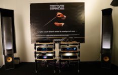
I was turned on to electrostatic loudspeakers at the Helixir Audio stand at the High End Munich 2016 (picture attached). The guy at the stand had a small room and was actually just selling the electronics to his obviously self-built loudspeakers, but my accompanying friend and I returned to that room often that day. We really liked that guys loudspeakers. That same evening I found CharlieM's very instructive webpage Jazzman's DIY Electrostatic Loudspeaker Page and was set on building my own electrostatic speakers.
this is a build thread for my attempt at a constant dipolar directivity esl panel.
I was turned on to electrostatic loudspeakers at the Helixir Audio stand at the High End Munich 2016 (picture attached). The guy at the stand had a small room and was actually just selling the electronics to his obviously self-built loudspeakers, but my accompanying friend and I returned to that room often that day. We really liked that guys loudspeakers. That same evening I found CharlieM's very instructive webpage Jazzman's DIY Electrostatic Loudspeaker Page and was set on building my own electrostatic speakers.
Attachments
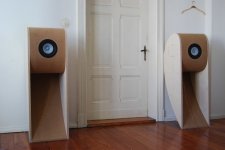
At the time I was listening on Alpair 12p hornreflex speakers. I paired the Alpairs with peerless woofers and two Hypex PSC2.400d amps as a first dipole experiment. This is my current setup and I already quite like the sound.
Since a few months I've been following up on my plans to replace the Alpair top unit with an electrostatic design. In the following posts I will get into the details of the design so far.
Since a few months I've been following up on my plans to replace the Alpair top unit with an electrostatic design. In the following posts I will get into the details of the design so far.
Attachments
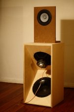
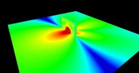
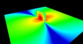
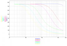
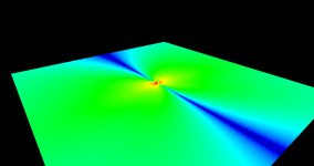
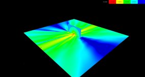
The inspiration to design for constant directivity comes from the Linkwitz page Linkwitz Lab - Loudspeaker Design. The Alpair dipole struggles at that from a few kHz on. The simulation pictures are 1.25kHz, 2.5kHz, 5kHz and 10kHz from left to right. The main takeaway from the pictures is, that once half the wavelength reaches the driver dimensions, directionality gets messy.
Attachments


If you want to use cone and planar drivers, you can create a constant directivity dipolar loudspeaker. There is no need to go the ESL route. That is a LOT of work!
Using a fullranger will fall short, as you have seen in your simulations. It will not have rear output above a few kHz. A multi-way loudspeaker would be a better way to do it, IMO.
Using a fullranger will fall short, as you have seen in your simulations. It will not have rear output above a few kHz. A multi-way loudspeaker would be a better way to do it, IMO.
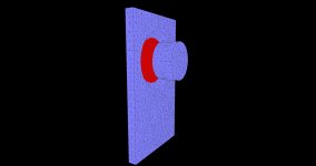
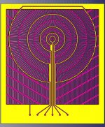
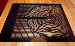
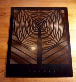
This is the current stator design. The conducting surfaces are separated into concentric rings or more precisely arcs. I want a lowering lowpass response as one goes from the center to the stator border (Keep radiating surfaces small in regard to wavelength). The diaphragm between two stators is supposed to be mostly driven by two opposing copper segments. I was not sure whether the RC filtering (like in most segmented wire esl's) could be achieved due to the cross cappacitance of coplanar conductor segments. I simulated the capacitance matrix of all the conductors in two opposing stators (second picture, also thumbs up for the fastercap software) and fed the result into QUCS. It seems one can still get really nice lowpass curves for the segments just by choosing an appropriate resistance for a panel input (third picture). The influence of the diaphragm was neglected in the 3d capacitance extraction. I hope it's not too bad.
Attachments

If you want to use cone and planar drivers, you can create a constant directivity dipolar loudspeaker. There is no need to go the ESL route. That is a LOT of work!
Using a fullranger will fall short, as you have seen in your simulations. It will not have rear output above a few kHz. A multi-way loudspeaker would be a better way to do it, IMO.
It's kinda too late for that 😉 A lot of time has already been spent. I also really want to see whether I can built a low distortion panel while achieving the desired directivity. I haven't really seen it done exactly like this before.
It's kinda too late for that 😉 A lot of time has already been spent. I also really want to see whether I can built a low distortion panel while achieving the desired directivity. I haven't really seen it done exactly like this before.
Since you have already begin, I wish you a very successful outcome! I think these ESLs are very interesting DIY projects. This kind of construction is totally out of my league, so I will be watching your progress here enthusiastically/voyeuristically!
I had the stator pcb's already built. I researched the design parameters in this forum, on some webpages and by doing some simulations/calculations. I had the stators made in 1.6mm fr4 pcb's. Holding them in my hand, the 1.6mm thickness seems alright, not too flimsy. The thickness necessitates facing the copper side towards the diaphragm. The stator-diaphragm-stator sandwich will (hopefully) be held together by 1mm thick and 19mm wide PET-foam-tape with acrylate glue. Tape will go around the outside of the slotted area and also up the middle over the signal supply lines, to keep the supply lines from exciting the diaphragm and to add structural support. Four tape spots might be added to reduce the dimensions of the unsupported diaphragm .
The slot width is 3mm and the support between two slots is a bit narrower.
Coplanar conductor spacing is 3mm. Opposing conductor spacing is 2mm. Sharp outer corners were avoided on the conductor (corona discharge).
Currently the only isolation on the pcb's is solder resist lacquer, I want to add a few coats of Plastik 70 by Kontakt Chemie. The design called for the copper to only reach up to 0.25mm close to the slots, so that more isolation around all of the copper could be built up by spraying lacquer onto the front. Unfortunately when milling the pcb, they added a little notch into each slot. The notches don't quite touch the copper, but there also isn't really an outstanding fr4 edge left.
Attachments
Last edited:
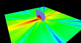
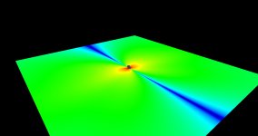
To achieve good dipole radiation, it is important that the stators don't obstruct the sound, more specifically the front-rear-wave interference, too much. I don't have optimized simulation software at the moment, so I had to restrict the simulation geometry to the first ring around the tweeter center (first picture). The results look rather promising. Middle picture is 12kHz, right Picture is 18 kHz. The sound output is about 10db down at 65° off-axis. The non-driven part of the diaphragm is left out. I assume that doesn't skew the simulation too much.
Attachments

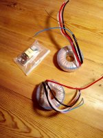
For the electronics I have bought two 50vA 230V 2x6v torroidal transformers from Sedlbauer per panel. I don't actually understand what makes a good esl transformer. I just know that the Sedlbauer's are supposedly "quality". Feedback on that topic is especially welcomed. The hv-supply will be based on a little inverter with an lm317. The design is mostly from this site main. The transformers will limit me to 4kV. As mentioned earlier, the panels will each be driven by a Hypex DSP2.400d. The targeted bandwidth is 180hz-20kHz with a steep crossover.
I forgot so far; overall panel dimensions are 44cm height and 38 cm width.
I forgot so far; overall panel dimensions are 44cm height and 38 cm width.
Attachments
Last edited:
There are many wonderful qualities to ESLs, of which being dipoles is only one.
My first ESL experience was the Jensens tweeters added to speakers like AR-3 "acoustic suspension" boxes. I doubt these played below 1.5kHz. But I was struck by their clean clear sound and, by the way, they were just in boxes with no rear wave coming out.
The Jensens (and many other ESLs) can be made from small cells mounted on a round frame. No problem with beaming.
My point is that building an ESL driver is great even if it isn't dipole and even if it doesn't cover much of the frequency range.
B.
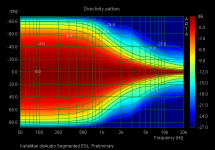
What is your desired directivity? Is it truly constant dipolar directivity? or slowly increasing with frequency. It will be very difficult(impossible?) to achieve true dipolar directivity at all frequencies using resistive filtering only. Based on the segmentation layout and lowpass curves you posted, attached is a rough estimate of the polar response....I also really want to see whether I can built a low distortion panel while achieving the desired directivity. I haven't really seen it done exactly like this before.
I posted some details of a method developed by Tim Mellow to achieve constant dipolar directivity with ESL by emulating an oscillating sphere:
Description and Links:
Quad 63 (and later) Delay Line Inductors: Post #225
Further details, directivity plots, and comparison with Quad ESL63 model:
Quad 63 (and later) Delay Line Inductors: Post #236
Directivity plots for practical passive implementation:
Quad 63 (and later) Delay Line Inductors: Post #262
Attachments
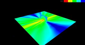
Thank you for your input bolserst. You seem to be right. I did some simulations (left picture 5kHz, right picture 10kHz). That overall matches your prediction. I guess the lowering of the input signal of the outer segments is dominated by their larger radiation surface!? Dang, thats what I get for being tired of simulating (the capacitance extraction took some time) and wanting to start building. May I ask, how did you generate that directivity pattern? (expert software, analytical insight?) Could you make a directivity pattern of a simple rectangular panel of same proportion for comparison?
Also regarding continuing the specific design, I can't think of an easy way to steepen the low-pass passively after the transformer. I really like the Mellow design, as it seems to work; but it's not a save for me, because my outer rings get too thick for even high frequency distribution.
Also regarding continuing the specific design, I can't think of an easy way to steepen the low-pass passively after the transformer. I really like the Mellow design, as it seems to work; but it's not a save for me, because my outer rings get too thick for even high frequency distribution.
Attachments
KlleMan, Your stator seems to behave like a perfect dipole point source! I've been thinking and dreaming of something like this, but I have no means to mak it real...
Naturally width will become a limiting factor for low freq range and spl. I am eagarly waiting for measurements!
Naturally width will become a limiting factor for low freq range and spl. I am eagarly waiting for measurements!
i just read more about FrontRo speakers designed by Tim Mellow
Design — FrontRo
The panels seems to be roughly 12" wide and plays from 600Hz up. Info doesn't tell the slope of xo to a tiny 5,25" woofer (monopole?), but with that size spl capacity must be rather limited...
Design — FrontRo
The panels seems to be roughly 12" wide and plays from 600Hz up. Info doesn't tell the slope of xo to a tiny 5,25" woofer (monopole?), but with that size spl capacity must be rather limited...
KlleMan, Your stator seems to behave like a perfect dipole point source! I've been thinking and dreaming of something like this, but I have no means to mak it real...
Naturally width will become a limiting factor for low freq range and spl. I am eagarly waiting for measurements!
As bolserst pointed out, it doesn't seem to work out that way. He has attached a directivity plot. I'm back to the drawing board.
Ps.: The last sim pictures I posted could be falsely interpreted. There's already a 15db drop off from mid of the center lobe to its boundary... It might look better at first glance than it really is. A directivity plot is much better to get the general picture.
Last edited:
I simulated the capacitance matrix of all the conductors in two opposing stators (second picture, also thumbs up for the fastercap software) and fed the result into QUCS. It seems one can still get really nice lowpass curves for the segments just by choosing an appropriate resistance for a panel input (third picture).
I'm checking, whether I can steepen the filter curves, by adding more rc-Filtering stages. I find the capacitive cross-coupling to be a limiting factor so far, but I'll investigate further. I constructed an equivalence circuit from the capacitance matrix in QUCS, but it's kind of a mess to work with... The ladder topology that people use on their segmented wire esl's also needs further investigation.
Attachments

Last edited:
From the point of view of "the worm" (rather than "bird's eye"), you need to ask about the seated human. With a mic or an ear at the seat, directivity can be unimportant, depending on the contribution of the room sound.
With directivity almost always a significant reality for speakers, you need to put together the results of direct sound, directivity, and absorption.
BTW, from my statistically oriented POV, a dipole helps a lot by mushing up the sound impingements.
With directivity almost always a significant reality for speakers, you need to put together the results of direct sound, directivity, and absorption.
BTW, from my statistically oriented POV, a dipole helps a lot by mushing up the sound impingements.
I do appreciate your point. My perspective right now is; I followed the argument for constant directivity. ( I guess, mostly the spectral composition of reflections from the POV of the worm.) I set out build this specific thing. I'd like to see it through; meaning, there are still some filter configurations to consider. If it works out; great. If not... I guess some other design it will be. I'm certain, there is a lot of fun and glorious sound to have with other esl approaches. Do you have a favorite one?
Not possible with ESL to get this kind of controlled directivity?
Acoustic Horn Design – The Easy Way (Ath4)
Acoustic Horn Design – The Easy Way (Ath4)
- Home
- Loudspeakers
- Planars & Exotics
- An attempt at a constant dipolar directivity esl panel