Hello fellow planar lovers.
My name is edwin and i come from holland. I already have restored succesfully an audiostatic es100.
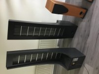
I recently acuired a pair of audiostatic esh50 speakers. It looks that the electronics are in good shape. But of course i have to change the mylar because there is not much sound to hear from the speakers.
But i have a few questions regarding the electronics.
In the photos you can see that there is an potentiometer in the cockroft walton electronics. Is this for pairing the sensitivity of the panel with the woofer?
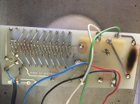
How much tension does the mylar aquire for the panel? Tight or a little loose like the es100. A can see that there are silicon dots on the panel.
The woofers are still ok. But if they dont sound ok wich woofers can i use as a replacement?
Does this speaker need a big amp like the es100 or can i do with alittle less because there is a woofer in the lower range that doesnt need much power.
Thanks for the answers.
My name is edwin and i come from holland. I already have restored succesfully an audiostatic es100.
I recently acuired a pair of audiostatic esh50 speakers. It looks that the electronics are in good shape. But of course i have to change the mylar because there is not much sound to hear from the speakers.
But i have a few questions regarding the electronics.
In the photos you can see that there is an potentiometer in the cockroft walton electronics. Is this for pairing the sensitivity of the panel with the woofer?
How much tension does the mylar aquire for the panel? Tight or a little loose like the es100. A can see that there are silicon dots on the panel.
The woofers are still ok. But if they dont sound ok wich woofers can i use as a replacement?
Does this speaker need a big amp like the es100 or can i do with alittle less because there is a woofer in the lower range that doesnt need much power.
Thanks for the answers.
Attachments
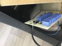
Correct…there is an potentiometer in the cockroft walton electronics. Is this for pairing the sensitivity of the panel with the woofer?

Crossover to the bandpass subwoofer is pretty low(~100Hz), so you will want tension similar to the ES100 with the silicon dots.How much tension does the mylar aquire for the panel? Tight or a little loose like the es100. A can see that there are silicon dots on the panel.
Based on the attached brochure, I would anticipate you will need similar amp size to what you use for the ES100 to get similar SPL.Does this speaker need a big amp like the es100 or can i do with alittle less because there is a woofer in the lower range that doesnt need much power.
Attachments
Thank you for your answer.
There is an 30 microfard condensator in series with the panel. Perhaps i will try to fit in a parallel coil so it will be a twelve db octave filter for better power handling. Just trying.
And later on, when the panels are restored, i will make the woofers active so the amplifier will have less stress.
Thanks for your anwers bolserst.
Edwin
Hi guys,
I while ago i finished this project ofthe esh50
But i noticed that it is almost impossible to get the woofer work properly with the panel because you can hear a lot of resonances in the woofer cabinet. And the woofer sounds very sluggish. The crossover only concists of a little coil of 4.7 millihenry and a cap of 33 microfarad.
So i found a final s200 subwoofer. Recapped the plate amp and used it for the bass. And this sounds very good. The bass is fast tight an intergrates very well with only the panels. And it can play loud.
Buti noticed that when music is a little bass heavy and with only moderate soundlevels, the panels vibrate a lot. Thisis obvious because the panels cross at a 150 hz with only a 30 microfarad cap. That isonly 6db per octave.
Does anyone have a suggestion to release the panels from more base. For example an 12 db crossover? What value should the parallel coil be. I can experiment with the coils value. But i cant really measure the speaker.
Or should i go with an electronic crossover? The amp i am using is an NAD. So i can take the pre and poweramp apart for a crossover. If i go this route, does the 33 microfarad cap has to stayin place for dc offset?
Thanks for your help
Vibrating panels are a common issue in hybrid esls and my Martin Logans do suffer from that too. It probably is caused by the vibrations of the woofer. There is little to be done against it electronically. You could do some reinforcements of the bass enclosure like ceramic tiles or butimex padding on the inside. If the ESL panel is shaking along with the bass maybe some supporting rod halfway the panel may help.
But i am not usingthe bass woofers anymore. I am using a seperate subwoofer. A final s200 sub.
And i do think that things wil get better if the panel dont have to play bass notes
Gr edwin
And i do think that things wil get better if the panel dont have to play bass notes
Gr edwin
Even though it would mean a total rebuild of the frame, the woofer should be separated from the panel frame if you want it’s influence to be eliminated
A benefit in time alignment would be possible also since the woofers acoustic impulse center is hardly ever at the voice coil.
Along with the delayed crossover adding to it, you would have to pull the woofer forward for proper alignment anyway
Getting rid of DSP processing is a plus a far as I,m concerned. Do it naturally with less electronic signatures...,.
The way mfgrs. build this compromised construction mess doesnt mean DIYers have to compromise thankfully
Regards
David
My guess is that the ESL vibrations at low frequencies are coming from the un-damped diaphragm resonance. If you could make a measurement with the microphone 2cm from the ESL we would be able to see which the frequency and Q of the resonance is and decide how best to deal with it....Does anyone have a suggestion to release the panels from more base. For example an 12 db crossover? What value should the parallel coil be. I can experiment with the coils value.
One option is to acoustically damp it with felt or acoustic mesh as shown here:
Compare response in post#3 with post #44
Audiostatic baffle step filter: Post#3
Audiostatic baffle step filter: Post#33
Audiostatic baffle step filter: Post#44
The other option is to increase the slope of the crossover, as you suggested.
You mentioned the series capacitor is 33uF. I can't quite tell from the pics you posted, is there a resistor in parallel with the transformer input as described here?
What X-over for a hybrid ESL?
Martin Logan CLS Power Supply
If not, adding this resistor may solve your problem. If not, I’ll see about recommending a coil/resistor combination that will result in a damped 12dB crossover.
Hi bolserts,
I am not able to measure my audiostatics. Perhaps it is a good idea to get some gear to measure my speakers.
But back to bussiness.
I will try to built some of those acoustic solutions.
And there is no parallel resistor on the transformers, so the input cap of 33 microfarad is doing its work alone. So if you have any proposals for the filter, that would be great.
Thank you very much for al the help.
Greetings edwin
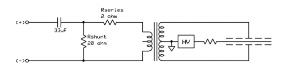
Attached is proposed filter.… there is no parallel resistor on the transformers, so the input cap of 33 microfarad is doing its work alone. So if you have any proposals for the filter, that would be great.
Without knowing the exact parameters of your transformer, the values are estimates.
Rshunt will affect the roll-off of the HP filter and should be in the range of 10 ohm to 47ohm.
Larger values will let more bass thru, smaller values result in less bass.
Rseries will affect the treble response and should be in the range of 1 ohm to 5 ohm.
Smaller values will result in boosted treble response, larger values result in rolled off treble.
***NOTE*** The Rshunt resistor will need to be able to handle significant power.
Lower powers can be used for testing, but for long term installation I'd recommend 50W.
Attachments
Thank you bolserts,
I have been busy with measuring equipment. And i have been interested in a company from your country, audiotools. Perhaps you know the company?
I have bought there ios app in the apple store. Now i am looking for a measuring microphone. Dayton audio has one in there programme that can work with the audiotools app. I am excited to begin with measuring my speakers.
For now thank you for all your help
Greeting edwin
Safety precautions
Hello bolserst,
Thank you for all your help in rebuilding my esh 50 audiostatic. I have used your recommandations in the crossover. I have installed a 10 ohm 50 watt resistor parallel with step up trafo. And it works perfectly. The speakers are more easier to drive. And it sound much better at the crossover point.
I usethe speakers with a subwoofer. And the combination is very satisfactory.
But i have a auestion regarding the high voltage cascade. Audiostatic always used the basic 230 volts mains without a trafo. So for safety i want to use a trafo with 230 volts in and 230 volts out. How much current is this trafo have to be at least?
Greetings edwin olthuis
Glad to hear the high pass filter is working well for you. 🙂
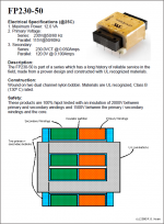
The high voltage supply uses very little current. Any transformer rated for more than 50mA or 10VA will work find.
Something like the TRIAD FP230-50, or similar.
FP230-50 Triad Magnetics | Mouser Nederland
The high voltage supply uses very little current. Any transformer rated for more than 50mA or 10VA will work find.
Something like the TRIAD FP230-50, or similar.
FP230-50 Triad Magnetics | Mouser Nederland
Hi Edwin,
Did you consider the circuit of E.Fikier; using two small trafoos connected in series with their low voltage windings? Their might be some voltage loss so you may have to check the output voltage of the cascade.
Did you consider the circuit of E.Fikier; using two small trafoos connected in series with their low voltage windings? Their might be some voltage loss so you may have to check the output voltage of the cascade.
Thanksfor your answers bolserst and mj dijkstra.
Now i can go further wirh this project. I think i have the book of fikier somewhere digital stored in my network NAS. Soi will look up this technique wich you mentioned mj dijkstra.
Greetings edwin
Now i can go further wirh this project. I think i have the book of fikier somewhere digital stored in my network NAS. Soi will look up this technique wich you mentioned mj dijkstra.
Greetings edwin
Two transformators e fikier
Hello mr dijkstra. I found the theoretics on the high voltage cascade. Do you mean this particular piece? See attachement.
I dont understand exacly why you would loose some high voltage. Can you explain?
Hello mr dijkstra. I found the theoretics on the high voltage cascade. Do you mean this particular piece? See attachement.
I dont understand exacly why you would loose some high voltage. Can you explain?
Attachments
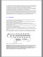
Yes! This is the schematic.
The output of the second trafo will be slightly lower than 230 Volt because of some losses. In case of the very large cascade of Fikier this is no problem as this cascade will deliver about 5,5 kV (but not the mentioned 7,5 kV) and this voltage suits the ESL very well.
If you put the 2 trafos in front of the original audiostatic, you may feed the cascade with a slightly lower voltage hence my recommendation to check the output.
But what is the advantage of these two trannies instead of onr 230volt/230volt transformer?
Greetings edwin
Greetings edwin
But what is the advantage of these two trannies instead of onr 230volt/230volt transformer?
Greetings edwin
With the 2 trafoos you have a galvanic insulation between mains and cascade. So it is a safety issue.
Unless it is an auto-transformer, don't most power transformers provide galvanic insulation without needing to resort to the dual transformer setup? Come to think of it, if one transformer isn't providing galvanic insulation on its own, a dual setup wouldn't either right?
The TRIAD dual bobbin Flat Pack transformers are nice because they have plastic dividers built into the bobbins to ensure primaries and secondaries are kept separate from each other rather than just winding secondary over the primary. Specifications state primary/secondary isolation is tested at 2kV.
The TRIAD dual bobbin Flat Pack transformers are nice because they have plastic dividers built into the bobbins to ensure primaries and secondaries are kept separate from each other rather than just winding secondary over the primary. Specifications state primary/secondary isolation is tested at 2kV.
Attachments
- Status
- Not open for further replies.
- Home
- Loudspeakers
- Planars & Exotics
- Audiostatic esh50 renovation project