SLAM!
On the last pages in my old thread, Yet another DIY AMT, I were on the verge of starting to work on a new AMT motor.
But now when I'm actually starting, I want to make a clean start with a new thread.
This motor will be 150 cm long, that is how far my stash of pole pieces and magnets takes me.
I still have my doubts of an AMT line source, but the motor can be used for other configurations.
So Solhagas Long AMt is finally coming up!
First I need to do some OnShaping...
Last edited:
Do you have pole pieces for 2 AMT´s ?
This must be 3 or 4 membrane´s ,or what
Nice to hear from you again.
Bernt
This must be 3 or 4 membrane´s ,or what
Nice to hear from you again.
Bernt
Yes I have. But I'll will not mount any pole pieces on the back.Do you have pole pieces for 2 AMT´s ?
I haven't measured or heard any drawbacks of that approach.
It'll probably be a MMTMM configuration. The four Ms might be my usual full range membrane but cut off in the highs.This must be 3 or 4 membrane´s ,or what
Bernt
The tweeter will then be a new 45x45 mm AMT.
Hopefully this configuration deals with the vertical dispersion better.
Nice to hear from you again.
Bernt
Thank you, Bernt. Been busy building my CABS (Controlled Acoustic Bass System) system. Like all good things in loudspeakers - it's Danish.
Would a series of smaller AMT "stacked" have the same characteristics as a single large verdion?Yes I have. But I'll will not mount any pole pieces on the back.
I haven't measured or heard any drawbacks of that approach.
It'll probably be a MMTMM configuration. The four Ms might be my usual full range membrane but cut off in the highs.
The tweeter will then be a new 45x45 mm AMT.
Hopefully this configuration deals with the vertical dispersion better.
Thank you, Bernt. Been busy building my CABS (Controlled Acoustic Bass System) system. Like all good things in loudspeakers - it's Danish.
The simple answer is: no.
Mostly it will be less low frequency response and for sure the vertical dispersion will be different.
And a lot of useful membrane area will go to waste as there are return paths on the top and bottom of each AMT that could be 2 cm per AMT.
Are you thinking of letting all AMTs be tweeter size, that is 45x45 mm?
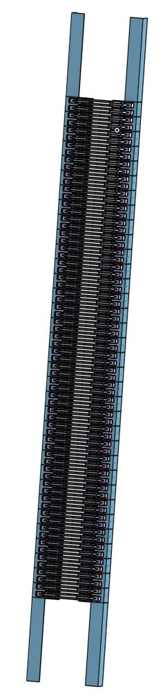
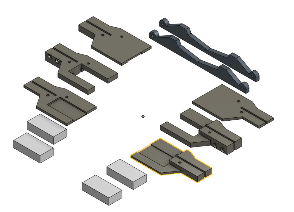
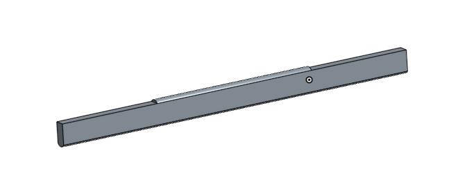
The result of a days work with OnShape.
Magnet and pole piece:
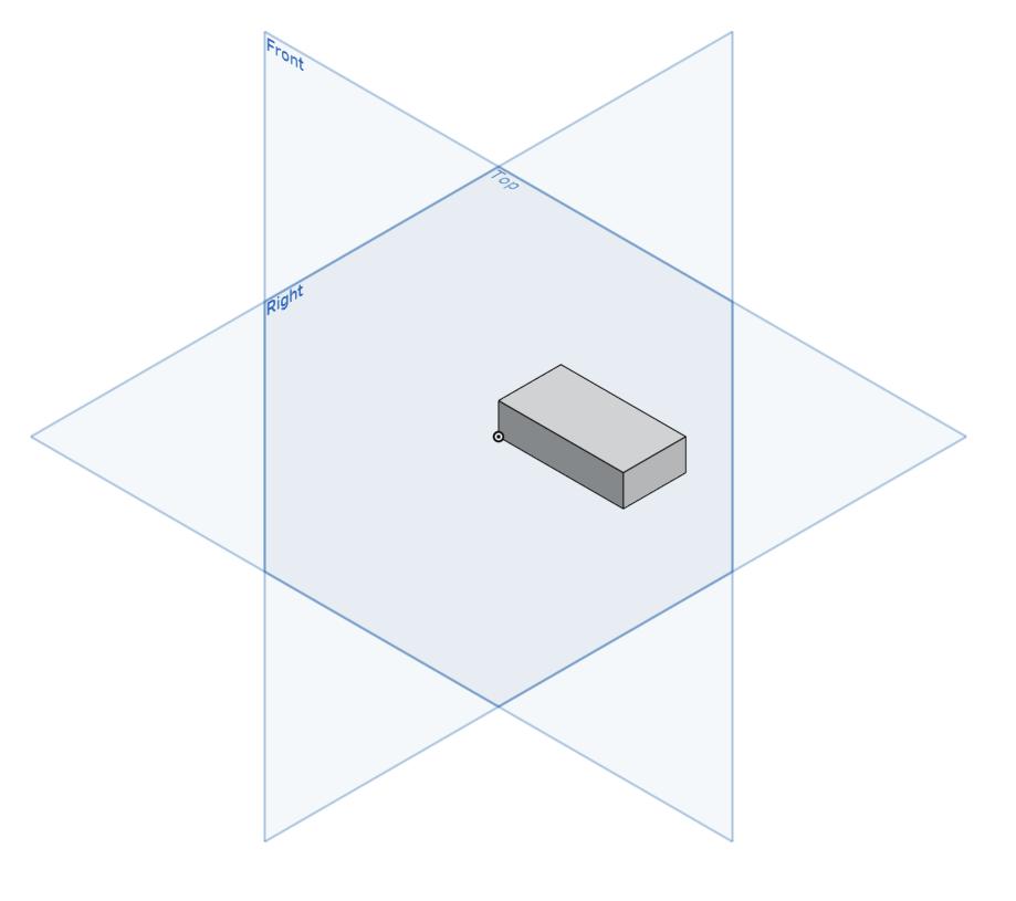
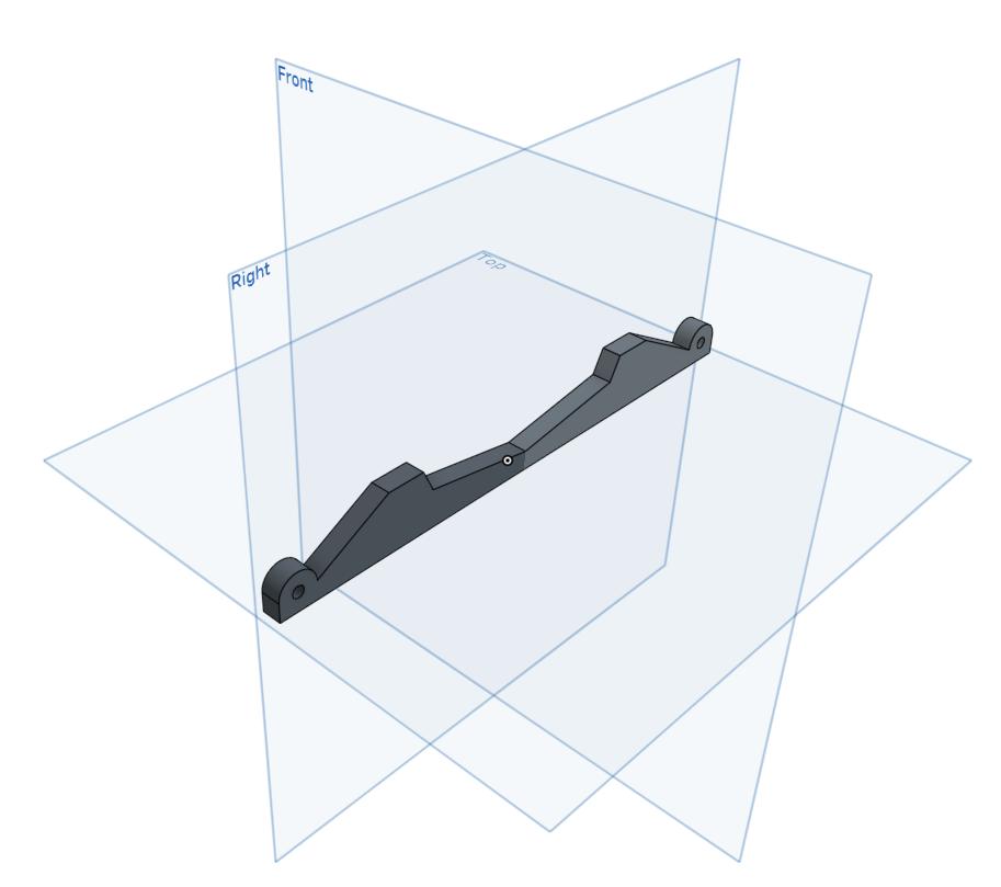
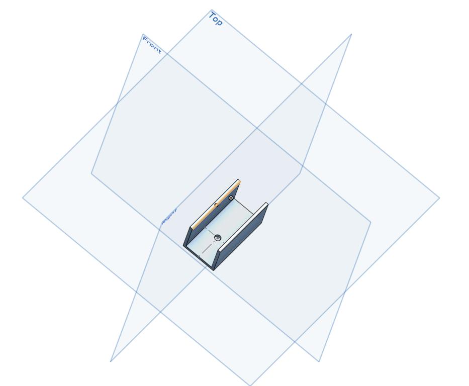
I'm doing a section of four pole pieces and then I'll multiply to the full AMT, so I need a smaller part of the frame:
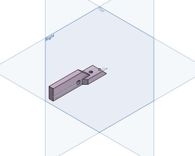
Pole piece hold:
 .
.
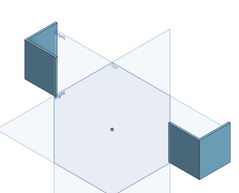
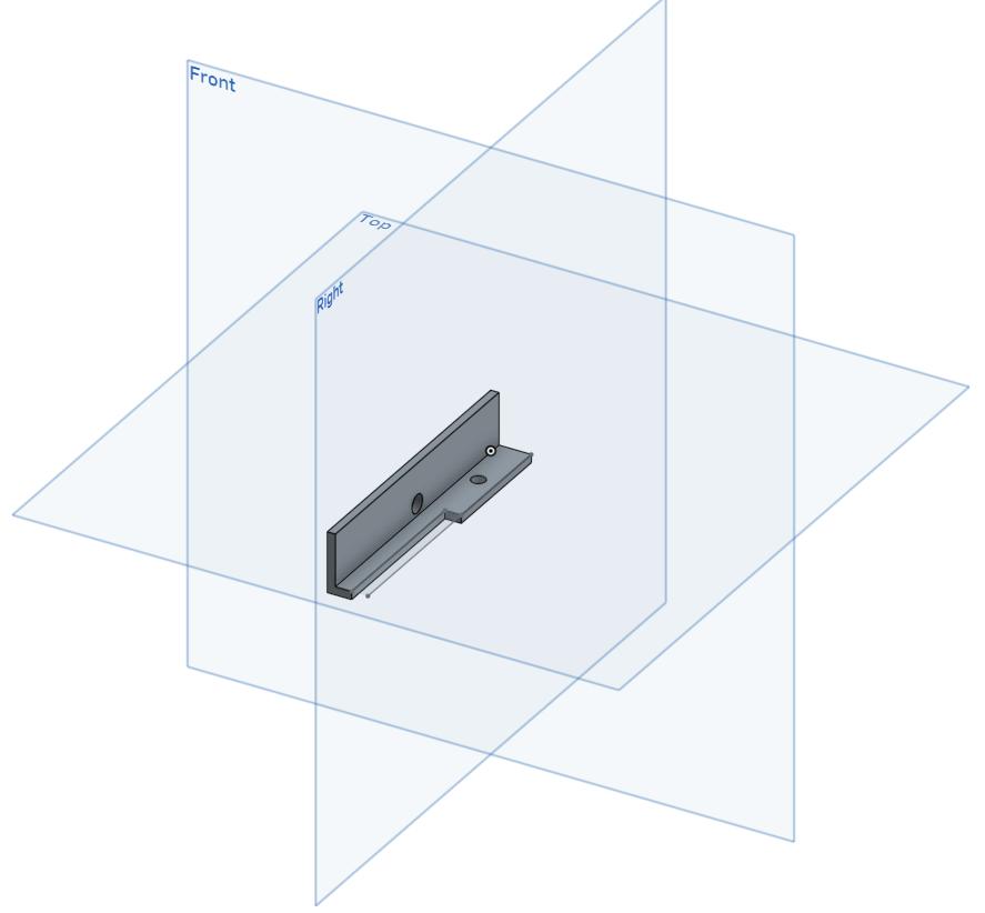
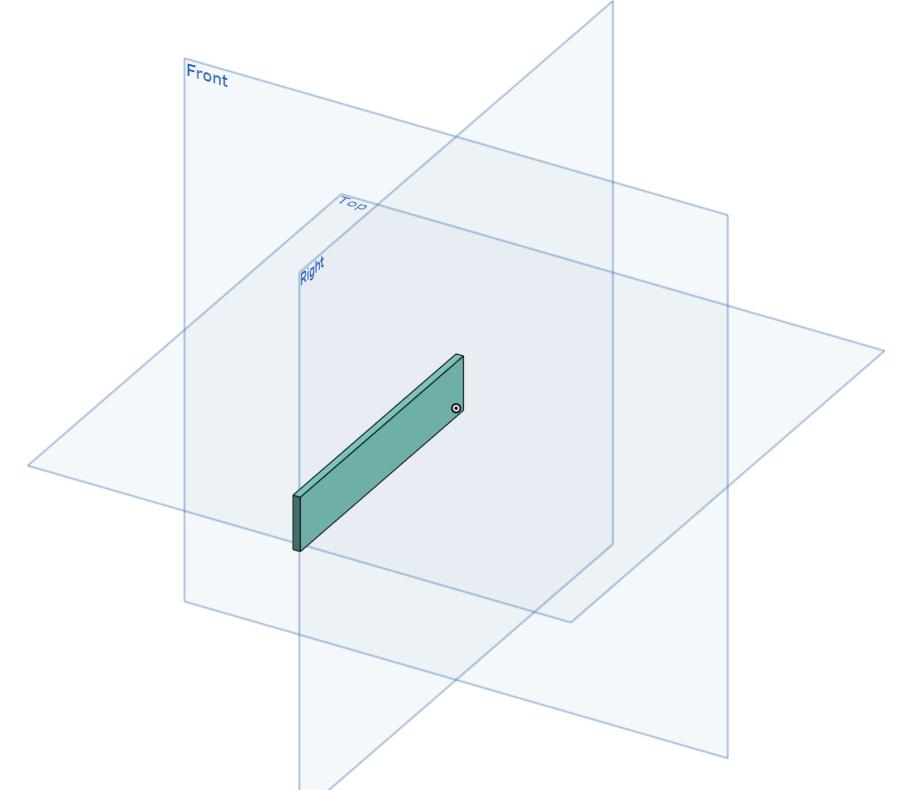
Spacer to hold a bar between the magnets and the bar itself:
There's a big chance that I can get 3D printed pole piece holders:
All the above in one four pole pice section:
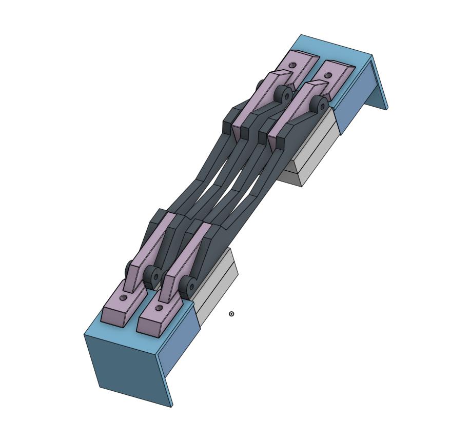
And...
SLAM!
Magnet and pole piece:
I'm doing a section of four pole pieces and then I'll multiply to the full AMT, so I need a smaller part of the frame:
Pole piece hold:
Spacer to hold a bar between the magnets and the bar itself:
There's a big chance that I can get 3D printed pole piece holders:
All the above in one four pole pice section:
And...
SLAM!
Nicee i am looking forward to this project 🙂 Nice to hear from you both 🙂 will keep an eye on this one !
I've decided to make the plastic parts myself.
So I've ordered the new Prusa i3 Mk3 3D printer.
Unfortunately it is not due until November...
So I've ordered the new Prusa i3 Mk3 3D printer.
Unfortunately it is not due until November...
Last edited:
Thank you, Wrinex.
Did you by the way visit any of the Piet Mondriaan exhibitions this summer?
🙂 not that I know of although I live in the Hague🙂
SLAM!
Got some prototypes made of the pole piece holders:
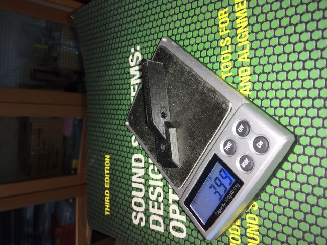
Some minor errors: fillet where the vertical part ends in the horisontal part should have had a larger radius and there should be no fillet on the bottom plate.
First try of the mounting:
The holders should have the same contour as the pole piece at membrane.
The backside, where the magnets will be mounted:
It could of course be good to cover the nuts with some snap-in so it'll be the same contour towards the membrane/gap all the way.
Test mount in the frame:

Got some prototypes made of the pole piece holders:
Some minor errors: fillet where the vertical part ends in the horisontal part should have had a larger radius and there should be no fillet on the bottom plate.
First try of the mounting:
The holders should have the same contour as the pole piece at membrane.
The backside, where the magnets will be mounted:
It could of course be good to cover the nuts with some snap-in so it'll be the same contour towards the membrane/gap all the way.
Test mount in the frame:

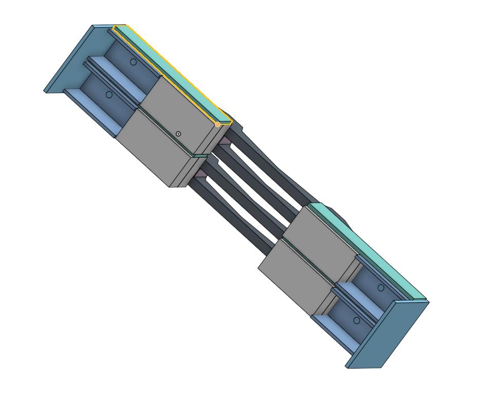
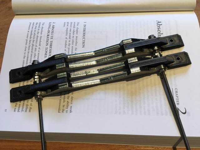
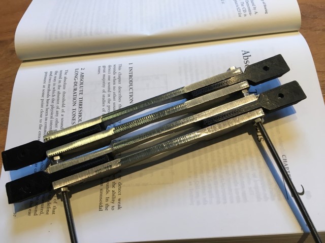
SLAM prototype v2
I'll replace the small aluminium parts with 3D printed:
I can then premount a complete two pole piece section (you'll have to ignore the aluminium part here):
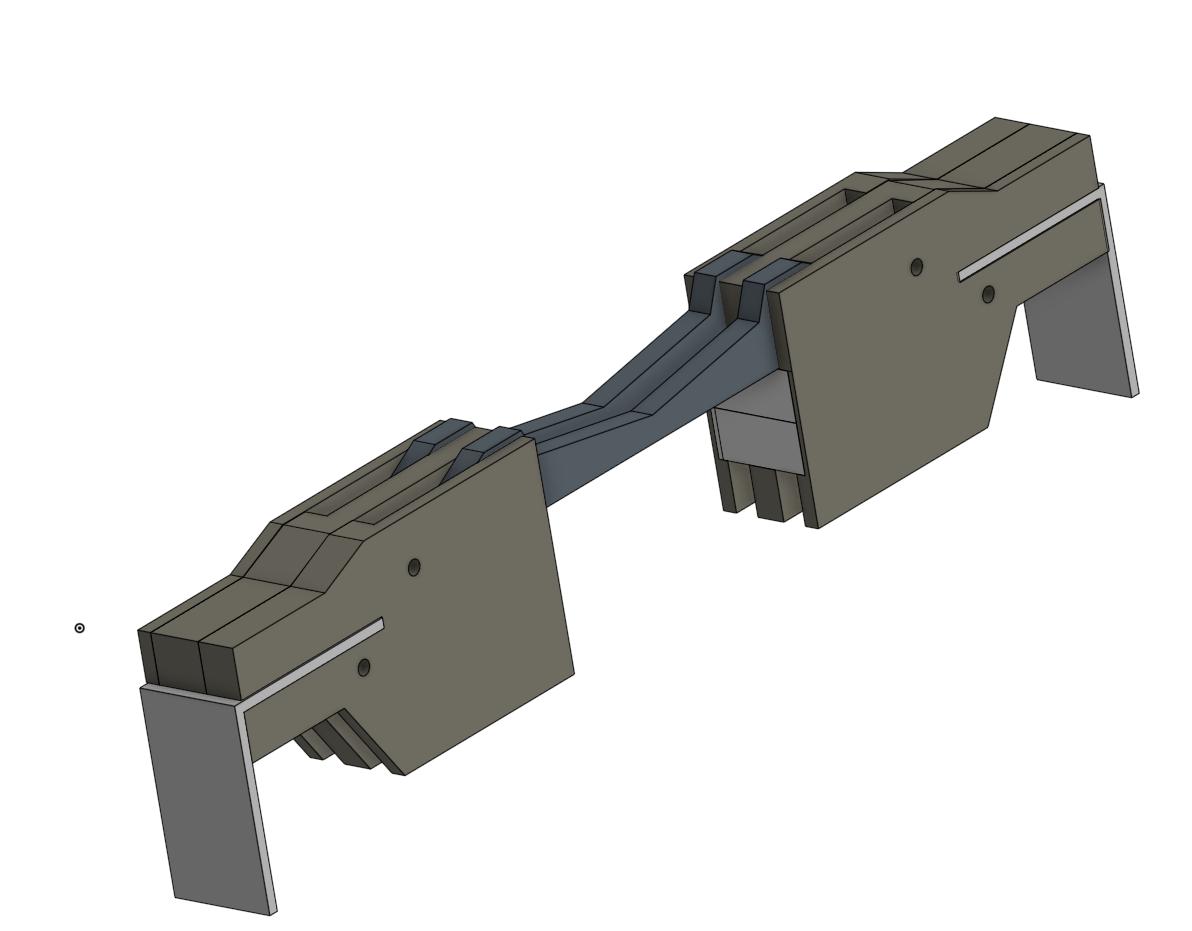
Another angle:
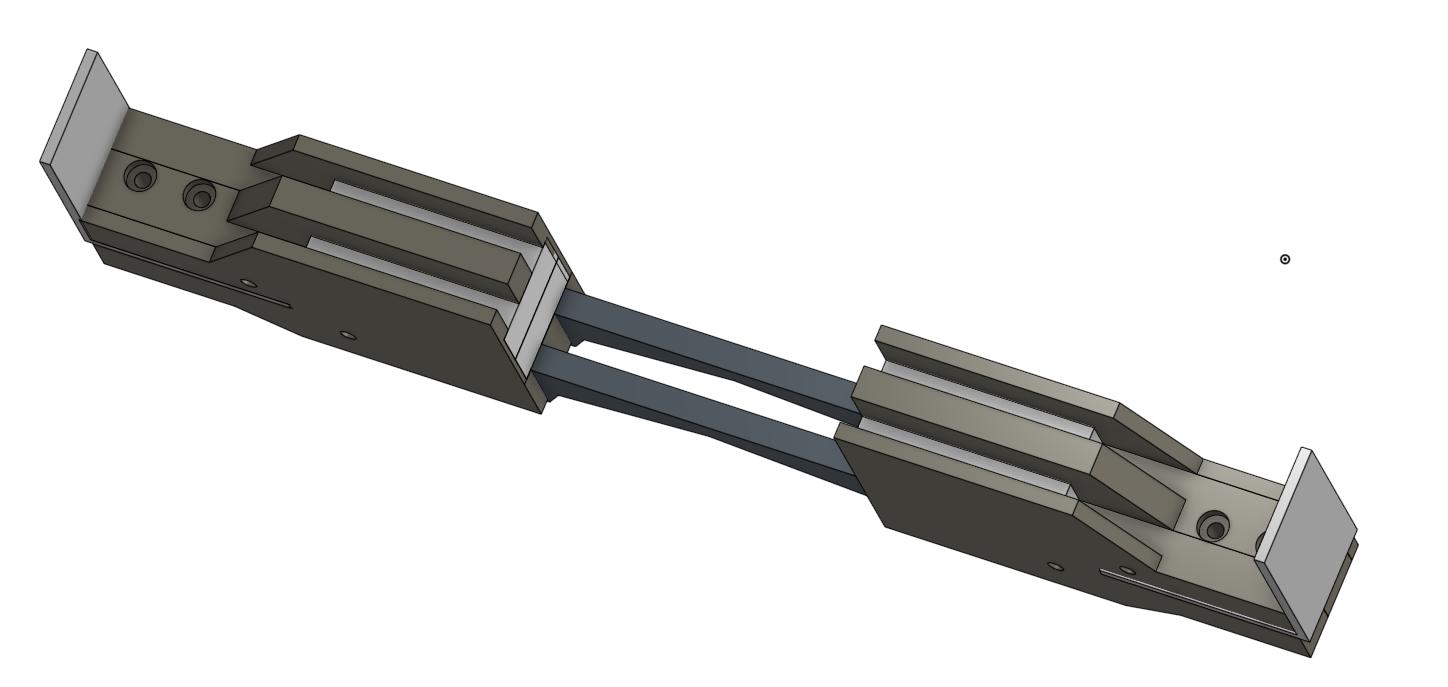
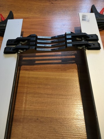
I'll force the sections down the aluminium frame "rail":
When in place I'll secure the section at the aluminium frame with a screw though the section and frame.
Hopefully will this be a lot faster and much more secure.
I'll replace the small aluminium parts with 3D printed:
I can then premount a complete two pole piece section (you'll have to ignore the aluminium part here):
Another angle:
I'll force the sections down the aluminium frame "rail":
When in place I'll secure the section at the aluminium frame with a screw though the section and frame.
Hopefully will this be a lot faster and much more secure.
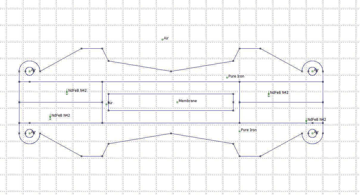
While waiting for the printer, I'll need some advice from the forum expertise.
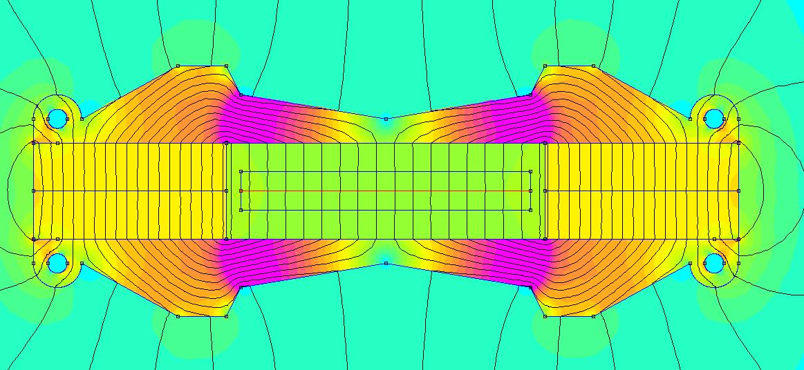
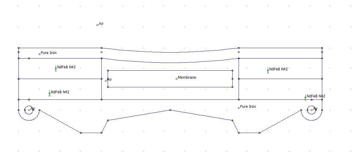
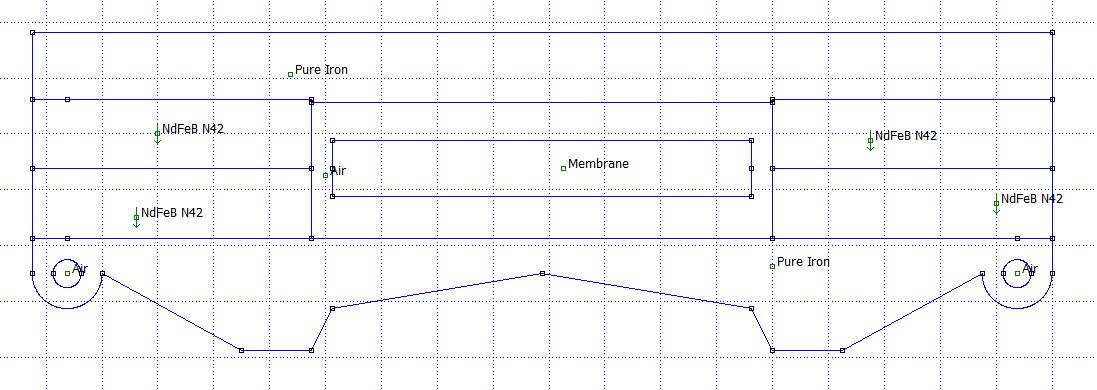
The ideal motor looks like this:
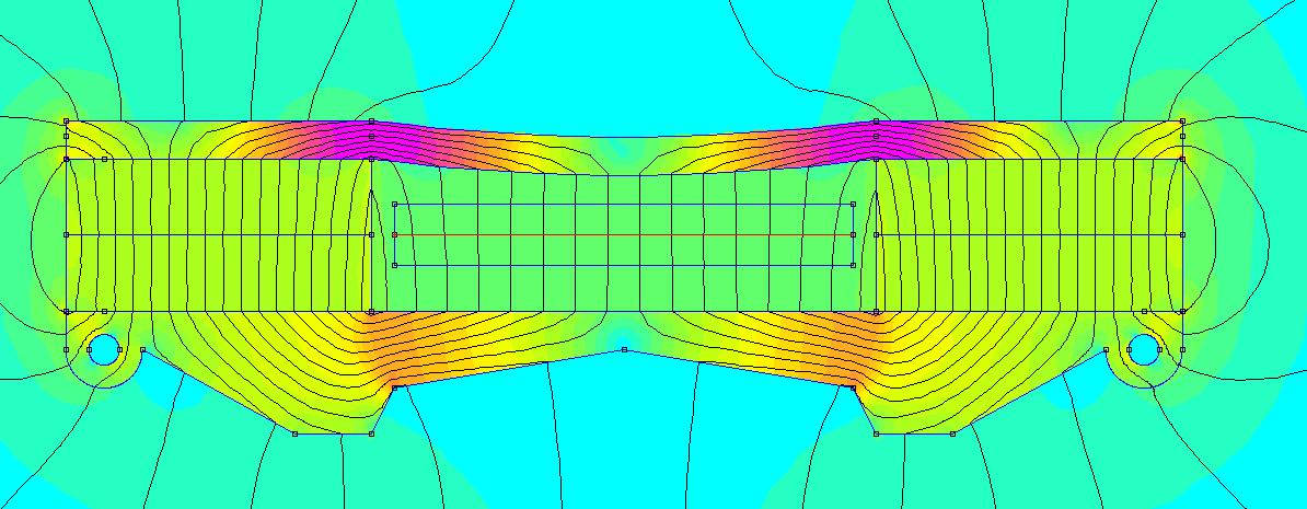
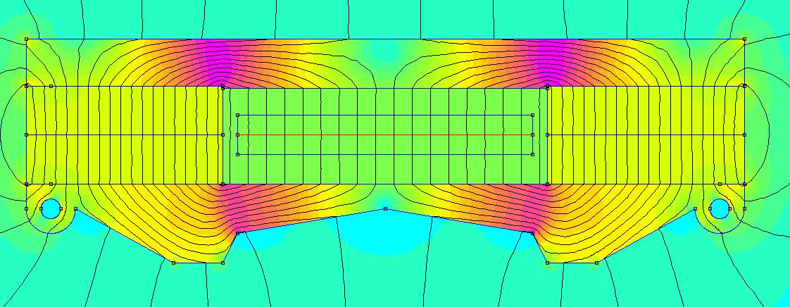
Simulated flux density:
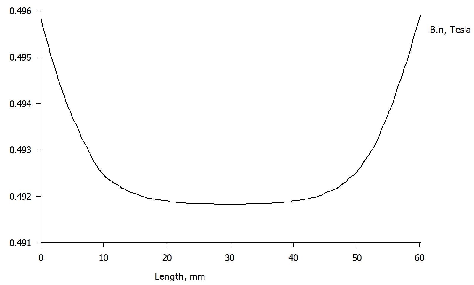
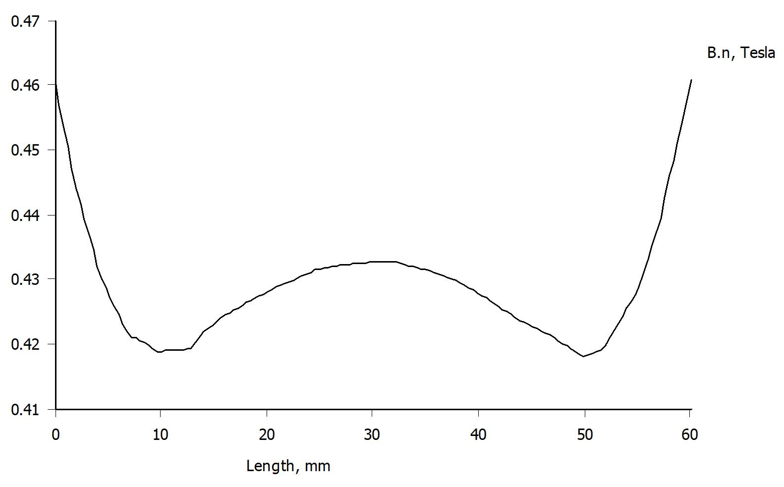
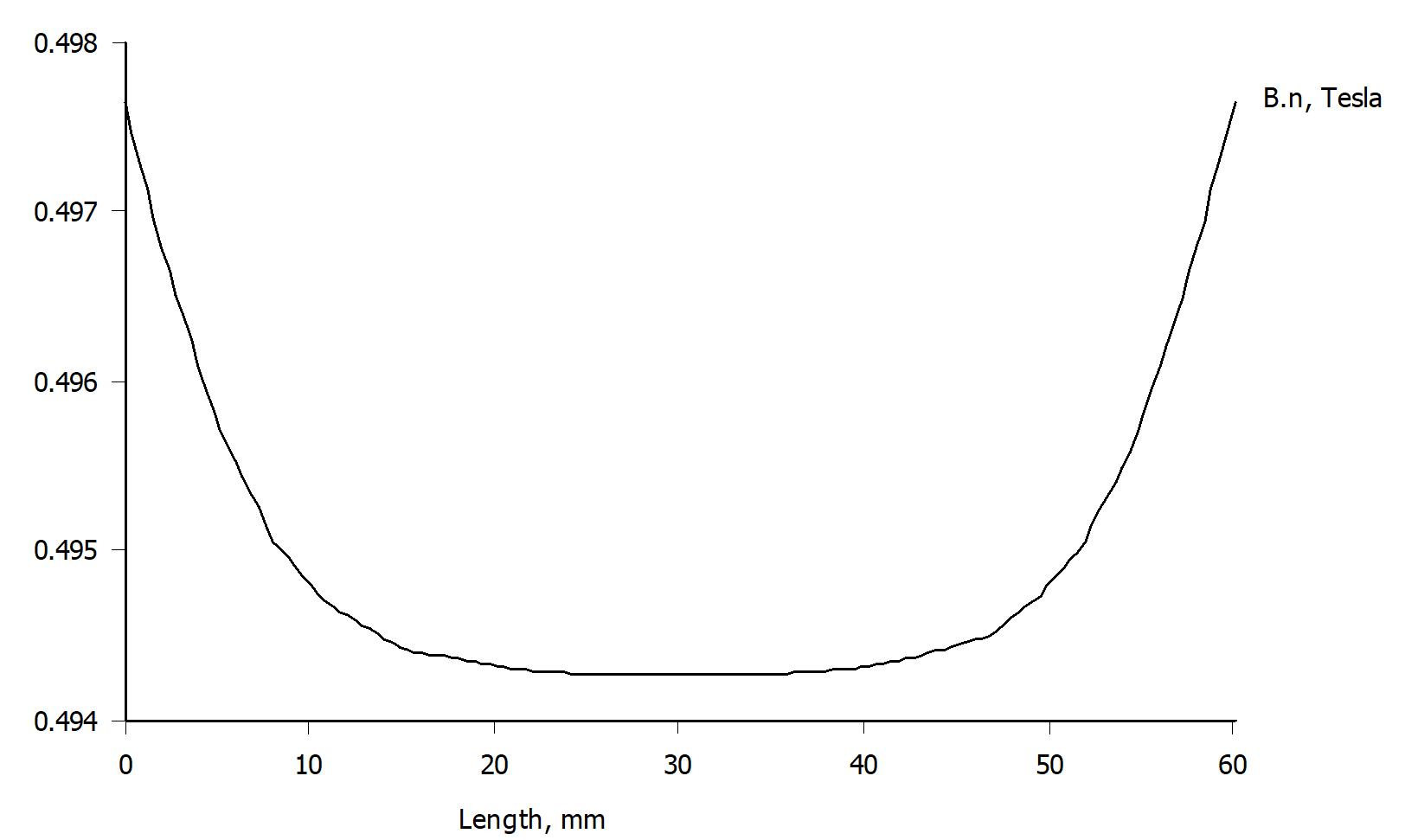
Horisontal plot:
Linear and even through the gap.
But the reflexion of the back wave produces all sorts of distortion both in time and frequency when it is mixed with the front wave.
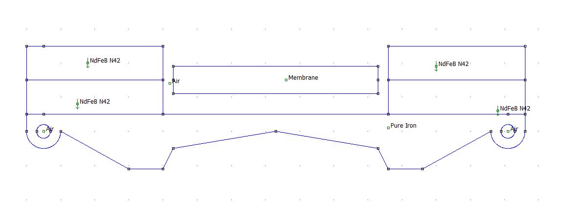
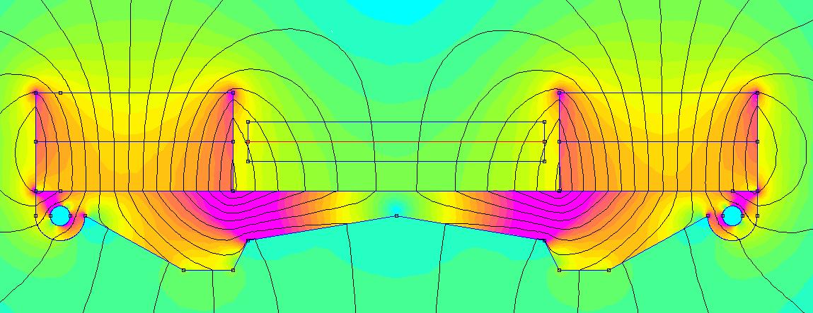
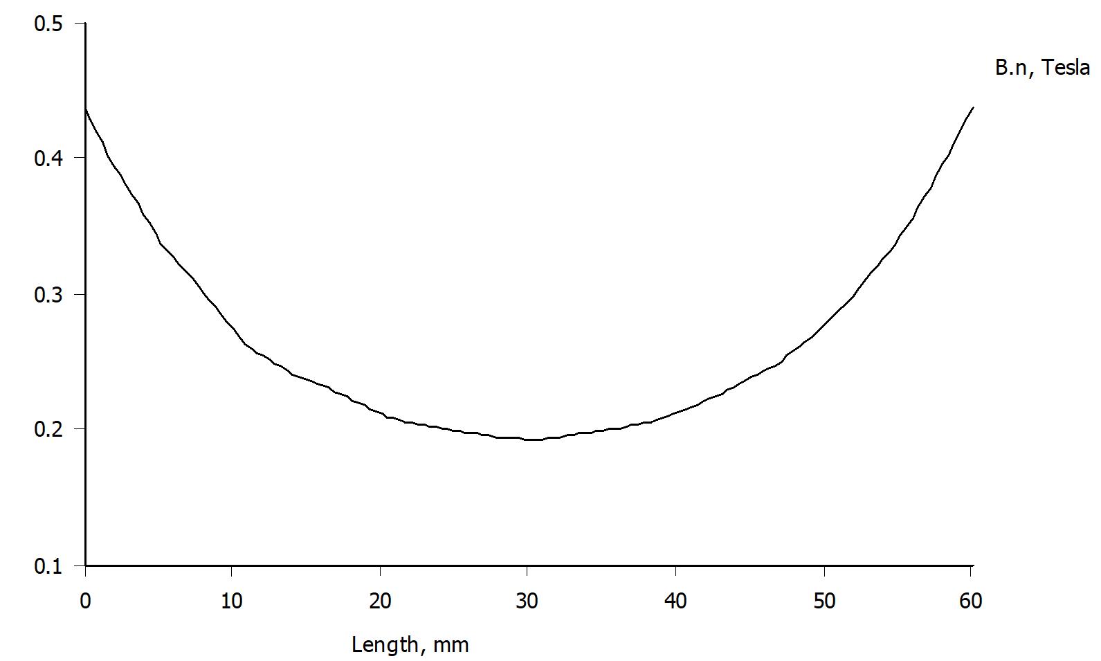
So after a couple of measurements with different back pole pieces, I decided to skip the back pole pieces all together.
The flux density is now un-linear and varies a lot over the gap.
Now I'm wondering if there a way to disperse the reflexion.
Considerably better linearity over the gap.
But is the back pole piece curved the right way to make the desired dispersian?
Shall it have a larger radius? (Larger radius means greater variation.)
Other thoughts?
The ideal motor looks like this:
An externally hosted image should be here but it was not working when we last tested it.
Simulated flux density:
An externally hosted image should be here but it was not working when we last tested it.
Horisontal plot:
An externally hosted image should be here but it was not working when we last tested it.
Linear and even through the gap.
But the reflexion of the back wave produces all sorts of distortion both in time and frequency when it is mixed with the front wave.
So after a couple of measurements with different back pole pieces, I decided to skip the back pole pieces all together.
An externally hosted image should be here but it was not working when we last tested it.
An externally hosted image should be here but it was not working when we last tested it.
An externally hosted image should be here but it was not working when we last tested it.
The flux density is now un-linear and varies a lot over the gap.
Now I'm wondering if there a way to disperse the reflexion.
An externally hosted image should be here but it was not working when we last tested it.
An externally hosted image should be here but it was not working when we last tested it.
An externally hosted image should be here but it was not working when we last tested it.
Considerably better linearity over the gap.
But is the back pole piece curved the right way to make the desired dispersian?
Shall it have a larger radius? (Larger radius means greater variation.)
Other thoughts?
The back pole piece can be straight across the gap to get a linear flux density.
Convex or concave curvatures towards the membrane are easily made from printed plastic details that are glued to the pole piece.
Convex or concave curvatures towards the membrane are easily made from printed plastic details that are glued to the pole piece.
Hi Solhaga
I don´t use back pole for my AMT´s.
Using back pole increases sensivity and give a much more linear magnetic field.
My idea is to use round bars to omit reflexions .
Use a angle grinder to cut the ends like this:
Bernt
I don´t use back pole for my AMT´s.
Using back pole increases sensivity and give a much more linear magnetic field.
My idea is to use round bars to omit reflexions .
Use a angle grinder to cut the ends like this:
Bernt
Hi Solhaga
I don´t use back pole for my AMT´s.
Using back pole increases sensivity and give a much more linear magnetic field.
My idea is to use round bars to omit reflexions .
Use a angle grinder to cut the ends like this:View attachment 641975
Bernt
Yeah, that's a great idea.
Instead of using a grinder, a 5x5 mm square rod can be used that can have your suggestion glued to it or a concave or a convex or a ...
As the configuration is MMTMM, the section where the four mid membranes are can have back pole pieces.
This as the reflections have little impact for that frequency interval.
I'm also considering to make the mid membranes to go lower, let's see what properties that will have to change - pleat depth, pleat width and/or foil thickness/width.
Then I will see if the small tweeter membrane in the middle can cope with back pole pieces.
That membrane's properties will of course be changed as well, apart from being shorter of course.
Back pole piece:
I will test this in my current motor.
Simulations looks good!
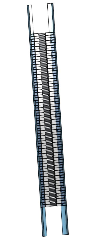
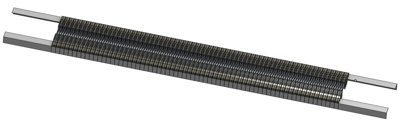
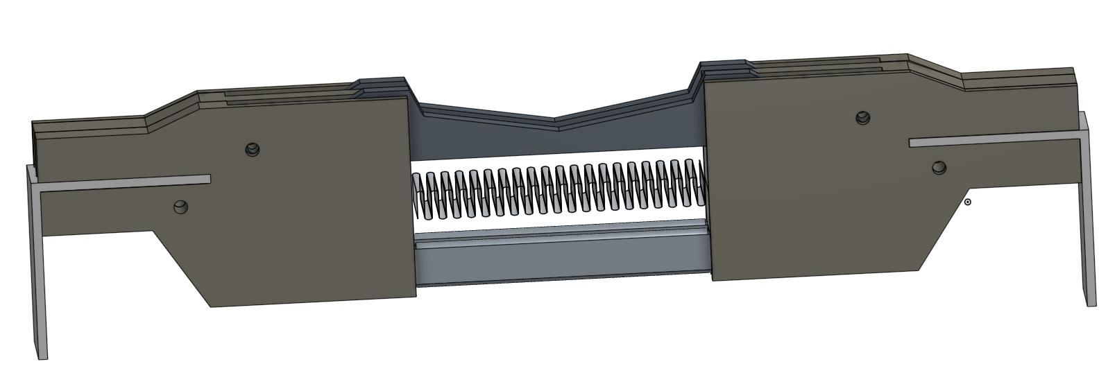
SLAM! two pole piece complete assembly:
This as the reflections have little impact for that frequency interval.
I'm also considering to make the mid membranes to go lower, let's see what properties that will have to change - pleat depth, pleat width and/or foil thickness/width.
Then I will see if the small tweeter membrane in the middle can cope with back pole pieces.
That membrane's properties will of course be changed as well, apart from being shorter of course.
Back pole piece:
An externally hosted image should be here but it was not working when we last tested it.
I will test this in my current motor.
Simulations looks good!
An externally hosted image should be here but it was not working when we last tested it.
An externally hosted image should be here but it was not working when we last tested it.
An externally hosted image should be here but it was not working when we last tested it.
SLAM! two pole piece complete assembly:
An externally hosted image should be here but it was not working when we last tested it.
Hi Solhaga
I have tried to become member at faktisk.se to make a comment to your SLAM project.
At the registration site you are given a security question to prevent spambots
In SWEEDISH.
A comment to the other site. You can increase the field strength in the tweeter gap using this bar:
Are the iron bars saturated ?
Bernt
- Status
- Not open for further replies.