Dear ESL constructors,
I was looking at an original broken Quad ESL 57 stator. Why more people don't use the very simple Quad ESL 57 way of making stators? Maybe its because DIY folk started doing it the Sauders way and just continued.
It looks relatively easy compared with using perforated sheet or wire mesh with all the resonance/kinking issues involved, especially if you want to make accurate stator gaps of 1 mm or less over a large area.
From looking at the construction its simply a thermoplastic in with indentations made by compressing the thermoplastic in a simple ring mold while heating. This way you just clamp the film to the stators and no separators are needed. You could even mold them from clear acrylic, though its harder to drill, The conductive elements are simply attached to the surface of the plastic. I guess Aluminium foil and some varnish would be easy and simple, but maybe you use wire mesh in the mold.
With the Quad ESL 57 attached the conductive material inside for the high frequencies and outside for the bass (making bass panels almost indestructible). Attaching the conductor (probably not to hard) and the mold is the only hard part now, but you only need to make one.
The mold could be made very easily with different thicknesses of MDF, or even the same thickness and depth adjusted with some spacers under the center board. All you would need is a jigsaw and a couple of clamps on a a compression ring on the outside while in the oven, when the clamps loosen take out of over and tighten clamps and repeat until molded. I imagine some thick low density polythene sheets about 5mm think or more would be ideal.
Looking at the final result from a damaged stator, it looks like the holes where drilled before attaching the surface or molding.
The Quad ESL 57 does not sound so bad as to go with more complex solutions? I accept that segmented PCB's in nice injection molded stator holders like the ESL 63 would be better but its a lot harder even than the metal grill approach.
I will be making headphones and will probably use PCB material as its small but for larger drivers the approach taken by the Quad ESL - 57 seems very practical and molding would provide good uniformity of stators, which I imagine is key to getting the stereo imaging I love about electrostatic speakers.
Regards
Owen
Hi,
Making a mold of sufficient precision just for the few DIY panels? Drilling countless holes, glueing conductive strips, insulate conductive areas, etc, etc. doesn´t sound all too easy to me.
The easiest and probabely most rewarding for DIY will still be the wired stator as materials are easyly and cheaply available and the chance of success is high.
jauu
Calvin
maybe, because it is in fact not that simple??very simple Quad ESL 57 way of making stators?
Making a mold of sufficient precision just for the few DIY panels? Drilling countless holes, glueing conductive strips, insulate conductive areas, etc, etc. doesn´t sound all too easy to me.
The easiest and probabely most rewarding for DIY will still be the wired stator as materials are easyly and cheaply available and the chance of success is high.
jauu
Calvin
Yes, making it by using mold is perhaps a quite difficult task.
But if one's has an access to CNC or perforation machine and sufficiently large PCB sheets then it could be quite viable IMO.
Searching through google shows typical PCB material FR-4 has a dielectric constant of about 4. So 1.5mm thick material would seem like some 0.3-0.4mm of air which is more or less acceptable.
However this has some quite serious issues with safety, as copper would be exposed to outside(same problem as with bare metal stators). The need for grounded conductive screen(s) complicates everything a lot.
After doing some experiments with sheet vs wire stators I never looked back to sheets of any kind(except I want to make a curved system in some future).
Regards,
Lukas.
I read about a build some few years ago of a DIYer made molds and poured his own acrylic stators.
He said that they turned out very nice and worked well and used them for mix down monitors in the studio where he worked.
But after some time he said they yellowed a bit and started to warp and lost their precision shape.
I have used Plastic lighting grid and it works well for small width panels but for anything larger it takes extra support in order to have a stator the doesn't bow in or out.
An 8" wide panel can be flexed quite a bit and still work but it took a lot of tensioning to make them stable and this caused each side to bow out alot by as much as .010" to .030" (much to much) or more sometimes.
I know one was pretty bad although it still worked okay and I don't remember the exact value as it was 10 years ago.
And that is using a rigid plastic grid material.
Plastic sheet that has no lateral support can be much worse!!
I recall one DIYer that had to find a new Tweeter panel for one of his 57's becuase it was warped and only slightly.
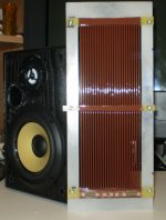
On my latest build I have gotten within +/-5 mil or so using TIG wire and I am still having a bowing issue with the PCB stator support.
It is not to bad but it is there and it irritates me!
I will correct this when I build the next one.
I am not sure if it was caused by heat from having to resolder and reposition the rods causing them to have tensioning on the PCB material and/or if the PCB's warped from being reheated so many times.
I did have to replace one end due to a few pads that lifted off from the heat.
My new frames are made of standard sheet plastic and have no rigidity to them at all and I was scared the this was going to be an issue.
But the TIG rods gave the panel some very good rigidity in the end and enough to support the mylar being sandwiched at 5" intervals with bolts.
jer")
He said that they turned out very nice and worked well and used them for mix down monitors in the studio where he worked.
But after some time he said they yellowed a bit and started to warp and lost their precision shape.
I have used Plastic lighting grid and it works well for small width panels but for anything larger it takes extra support in order to have a stator the doesn't bow in or out.
An 8" wide panel can be flexed quite a bit and still work but it took a lot of tensioning to make them stable and this caused each side to bow out alot by as much as .010" to .030" (much to much) or more sometimes.
I know one was pretty bad although it still worked okay and I don't remember the exact value as it was 10 years ago.
And that is using a rigid plastic grid material.
Plastic sheet that has no lateral support can be much worse!!
I recall one DIYer that had to find a new Tweeter panel for one of his 57's becuase it was warped and only slightly.
On my latest build I have gotten within +/-5 mil or so using TIG wire and I am still having a bowing issue with the PCB stator support.
It is not to bad but it is there and it irritates me!
I will correct this when I build the next one.
I am not sure if it was caused by heat from having to resolder and reposition the rods causing them to have tensioning on the PCB material and/or if the PCB's warped from being reheated so many times.
I did have to replace one end due to a few pads that lifted off from the heat.
My new frames are made of standard sheet plastic and have no rigidity to them at all and I was scared the this was going to be an issue.
But the TIG rods gave the panel some very good rigidity in the end and enough to support the mylar being sandwiched at 5" intervals with bolts.
jer
Attachments

Last edited:
Dear all,
Thanks for the discussion points. I think making the mold will be the easiest part, as I even made a similar mold when I was 15 at school (we had a lesson in Plastic memory and molding). All you would need would be 3 sheets of MDF. One to make a ring around the molding "top", one to act as the "bottom" of the mold. The "bottom" would have holes cut on it where a similar thickness of MDF would be placed in the holes. These filled holes would cause the raised bumps by putting some spacers under the filler blocks, and placed on the molds floor so making nice simple smooth indents in the plastic.
I believe this part of the project could be done in an hour or two.
Calvin's point "Drilling countless holes, glueing conductive strips, insulate conductive areas, etc, etc. doesn´t sound all too easy to me." is an important issue. geraldfryjr made some interesting points about structural issues, which are very relevant too, I guess these issues of structural issues are the reason that Quad ESL 57 almost has two tweeters next to each other when looking inside the stator, this might be just to solidify the structure.
Getting slightly off topic and discussing PCB material, Luka's point about PCB material being a good dialectric is interesting. I personally would like to know how to design 3 layer PCB's cheaply so only the middle layer had copper.
Thankyou guys for your thoughts.
Regards
Owen
Hi,
Slightly warped quad ESL 57 panels can be fixed by gently heating with a heat gun and restoring their shape. Not sure about long term stability but this seems to work.
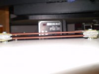
Why not make yourself life a bit easier and use wire that is already insulated? Single stranded PV3 or H07 are good candidates. Stability must come from supports where it is glued to. I have seen manufacturers using plastic for horizontal strips. Some plastics(eg. plexiglass) tend to crack and fracture so must be selected with care. I have used laminated plywood with success, but it has an disadvantage of being slightly conductive in higher humidity environments.
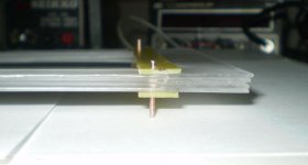
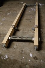
Wires must be stretched to straighten them(second photo is the stretching jig) and then somewhat released prior to gluing as no reasonable frame will handle the summed axial load of many wires.
Lukas.
I recall one DIYer that had to find a new Tweeter panel for one of his 57's becuase it was warped and only slightly.
Slightly warped quad ESL 57 panels can be fixed by gently heating with a heat gun and restoring their shape. Not sure about long term stability but this seems to work.
On my latest build I have gotten within +/-5 mil or so using TIG wire and I am still having a bowing issue with the PCB stator support.
Why not make yourself life a bit easier and use wire that is already insulated? Single stranded PV3 or H07 are good candidates. Stability must come from supports where it is glued to. I have seen manufacturers using plastic for horizontal strips. Some plastics(eg. plexiglass) tend to crack and fracture so must be selected with care. I have used laminated plywood with success, but it has an disadvantage of being slightly conductive in higher humidity environments.
Wires must be stretched to straighten them(second photo is the stretching jig) and then somewhat released prior to gluing as no reasonable frame will handle the summed axial load of many wires.
Lukas.
Attachments
Hi,
PCB stators have been discussed here at diy before afaik.
You may look at older Beveridge Patent US4,533,794 or Sanders US2005/0094833.
The Beveridge uses basically a single-sided PCB-Material with Nylon lamination insulation to the copper side, while Sanders is pure PCB-material and cnc-milling.
One is only restricted to the typical size limit of PCB-manufacturers for a pure PCB-stator.
jauu
Calvin
My new frames are made of standard sheet plastic and have no rigidity to them at all and I was scared the this was going to be an issue.
But the TIG rods gave the panel some very good rigidity in the end and enough to support the mylar being sandwiched at 5" intervals with bolts.
This new design looks great, sad to here about hte probelms with PCB material.
Regards
Owen
Thanks !!!
The PCB support is a small issue and will be corrected in the next one with a proper building jig to hold and space the rods while I am tacking the ends.
The second stator when together flawlessly and was perfect.
There are a few reason why I didn't use some common wire,
First there is the issue stretching and straightening the wire so that there are absolutely no kinks or ripples in them.
Not impossible to do, but very laborious!!
Therefore the rigidity of the steel rod is a big plus.
Although selecting rods that are completely straight can take some time as well.
Second I want to push the voltages to the limits with this panel as I have done so with my last one.
I can get nearly as much as 2Kv per mil of insulation factor using off of the shelf clear acrylic spray can paint.
Although my rod diameter is 1/16" a thinner wire and/or rods can be used as my last one used just window screen that was powder coated and then later painted seven years later.
I was able to push that panel with 10kv of bias and had as much as 25KV P-P across the stator's before the stator coating and sharp wire points caused it to fail.
These new stator's withstand 14KV (maybe more as that is the limit of my HV supply) each with no leakage problem with only 8 to 10 mil of coating thickness.
Third, I have tested some wire and it takes a pretty thick insulation to handle these types of voltages and it doesn't come on a thin gauged wire.
Kynar coated wire wrap wire is a great candidate and I have tested it at 10kv before. But, I believe that is about the limit for the common standard 30ga. stuff.
The cost of copper wire has gone through roof these days and it would still be quite costly to use it for even a small panel let alone a large panel!!
Steel has gone up as well but not quite as bad you can get a 10lb box of TIG rod for about $40 to $50.
There is about 35 rods per lbs.
And I already have some left over from the three 10.5" X 36" that I have finished.
I think I paid about $3 lbs 8 years ago or less.
It took 17 rods to make one panel.
So the cost of the pair of panels is about is less then $15 for everything including the paint.
10 years ago these cost probably would have been about half that.
I wanted to use common materials found down at the local hardware store and try not to revert to any special order items or exotic materials with the simplest method of construction that I could come up with.
Although I do have licron that I use for a diaphragm coatings, it has been reported that there are some materials commonly found on store shelves that may be some viable alternatives.
I got very good performance out of my last panels and it was by far the cheapest method of construction only I was pushing the voltages past what is I had designed it to do.
The stator coating was the biggest issue and I have perfected my method even using the window screen.
I just need to make a new pair of screens as I still have the frames for the diaphragms for them.
jer
Hi,
I agree that copper wire is not exactly cheap but it yields good results and is relatively simple to build larger panels this way.
The insulation is robust in both electrical and mechanical terms and can take a lot of abuse(including impacts with tools, etc). Breakdown of PVC is about 20kV/mm so typical PV3 or H07 wire should handle up to 10-13kV or so.
I have doubts if you can achieve similar levels of performance by using paint for real sized panels like 0.2-0.5m^2 square easily.
Also how did you test the insulation strength? Did you place the whole panel against an aluminum foil so there is no air gap and apply 10kV between it and stator?
I am not convinced that making a small panel with very high voltages is the best way to achieve good performance :
a) High bias will either need lots of tension or many supports to prevent the film from collapsing to a stator. This will rise fundamental mode a lot; other modes will be shifted to even higher frequencies
b) The need for very high step-up ratios makes life for the amplifier more difficult
c) Hissing/cracking noises during varying humidity levels can easily arise when air breakdown voltage is exceeded and air starts to ionize
d) Dipole cancellation for small panel is much more prominent limiting it to mid range & treble use, although this can be fought by using a baffle.
e) A line source of lets say 1.5m high or so would provide good vertical dispersion pattern which a small square panel would not
f) Long-term reliability test?
Regards,
Lukas.
Yes, I did properly test these stator's with a grounded probe touching the rods and there were no arcs.
I also show a test of window screen with the same method in the coatings thread in this forum.
PVC insulation is good for about 500v per mil as you mentioned I am getting at least 3 times that if not 4.
In order to achieve good performance with a small panel, large voltages are required as it has a much smaller surface area to work with.
I ran my last panel typically form 5KV to 7.5 Kv of bias and had pushed to to 10KV but it didn't last very long as the coating was aging.
It broke down frequently at those voltages after I made it to 25KV P-P on the stators and exploded.
Due to the type of construction it was nearly impossible to repair it and I would have spent much better time just making a new one.
A Desktop ESL Build
Many of theses picture are already in these threads, But things get buried quickly and it is getting more difficult to find them as I have made this same discussion many times.
Anyhow, That is when I started researching coatings and testing out what I had and found it to be very good actually if it was done properly.
To test the coatings I built a variable precision regulated HV supply so that when an arc occurs it will maintain the exact same voltage after the arc has stopped.
This way I can note what the voltage was when the breakdown occurred.
That project is in these threads and has been re-documented here as well,
Does anyone have schematics of a varible HV power supply
I don't have any humidity issues where I live at the moment and running it at about 4Kv to5Kv works very good just the same.
It took quite a few more coats of clear acrylic on top of the Powder coated screen to safely get to and above 7Kv.
Yes, I have been using about a 1:256 step up ratio in my final tests and it is difficult on the amp due to just the transformers capacitance alone as the panels capacitance is only 50pf.
At a 1:128 ratio they run very nicely but with a drop in sensitivity as expected.
I think at 1:128 and 7KV of bias I am able to nearly match the sensitivity of my woofer.
With two or three panels of the same size it matches up quite nicely and I found this to be about 1 sq foot or even the size of a piece of paper (8.5" X 11").
A normal 1:128 ratio works well too but doubling the ratio increases the sensitivity by 6db as does doubling the bias voltage.
If this was a larger panel this would not be necessary to achieve a high output.
I got about +105db at 1 meter with this panel at at less than 20v Peak into the transformer.
And no more than a 5V peak was all that was needed to be around 90db for normal listening.
My small amp was very happy with this range, and so was I! He,he,he,he.
I was trying to fully document this when I switched to a larger amp as the little one would shut down every time I hit a peak that it didn't like.
Being a cheapy cpu controlled cd player type it took for ever to go through all of the settings just to get back to square one with no EQ or DSP.
This is when the panel failed for the last time and it was just time to build a new one.
I was running the usual 20 P-P at about 105db pushed it a little farther and as I was sweeping the frequency up the very exact same spot that had been giving me problems had gave out.
I had, Had enough so I let it burn and watched the show.
It was a good test to see a much current the screen could actually handle as it got orange.
The after math of that test is some where in these threads as well.
These little panels were meant to be for nearfield listening at about .5 meter and did do incredibly well for this application.
Pushing the voltages is mainly just to see how far I can go to squeeze out every last gram of efficiency I can and find what the limits of the materials are.
Then to apply what I have learned to a more larger highly efficient panel.
I have had them so high that the air was ionizing in the gap but not arcing or distorting, although, it was so loud the it was difficult to tell without closing my ears.
After about 10 minutes the stator coating failed and it exploded from the side causing the plastic to catch fire.
I was using 4 cores at 1:64 each( total of 1:256) and the full output of a Crown DC300A II with 60v rails when this happened.
I am only after Mid/High frequency use for hybrid systems at the moment but you do need a good amount of D/S spacing for excursion's in order to get down to the 200HZ or 300hz range to help make up the difference of dipole cancellation's.
Thus the second reason for using such high voltages.
My next panel using the same design will be two 3 foot section and its width will be increased to about 6".
I will use that with my main woofer system.
Eventually I am thinking about using the same plastic grid and window screen design method to build some 8" to 12" wide X 4 foot long bass panels.
About 8 or 16 of them and corner load them in the room as in the David Lucas's design called the "Shockwave ESL Subwoofer System".
It will be interesting, But it will be some time before I get to that!!
My panels were 7 years old when I started pushing the voltages and survived any abuse I gave them up to that point.
The coatings never failed and the original Licron never deteriorated after many years of been environmentally been abused with sand and road salt as well.
In fact the panel that I burned up (much to my surprise) was using the original Licron formula (then 9 years old) and not the Crystal formula as I had thought.
I had only rediaphragmed one of them to do a side by side comparison and never re did the second one.
After 7 years they fired up the very first time and then I decided to clean them and eventually recoat them and start pushing the voltages.
So no reliability issues there, just as long as they weren't over voltaged !!!
jer
Last edited:
Using PCB would get you same result , or combining louvre like acoustat only for increasing rigidness, for smask panel you can get away with 1 mm PCB, I got a shity cnc I build for fun that coul mill all the holes and their copper around it so it won't arc. Use some paint for wooden floors to seal the copper side and ur done.
Plate of 1000mm x 500 mm x1mm thick is like 35 euro.
Plate of 1000mm x 500 mm x1mm thick is like 35 euro.
- Status
- This old topic is closed. If you want to reopen this topic, contact a moderator using the "Report Post" button.
- Home
- Loudspeakers
- Planars & Exotics
- Molding stators with plastic like ESL 57's.