Esl 63
Hi Buhl:
I am on the road away from home in Ottawa at the moment.
The long blink rate on the defective speaker may be caused by getting too low a voltage on the multiplier board.
If one or more of your new diodes are leaking or not soldered properly then you may be getting less than 5K volts on the board.
This may result in a longer blink rate because the lower voltage does not leak off at the same rate. The circuit charges up to possibly 3K or less volts and does not have the same potential to leak off as easily because the discharge path may be less conductive at a lower voltage.
Lower voltage will translate into a lower volume.
You could try swapping the good multiplier board. If the blink rate goes back to approximately 1 second and the panels operate as expected then you should replace the diodes again.
If you still have the same problem then you know it is not the HV board.
You need a gold leaf meter to test the voltage a regular high voltage meter will bleed the charge off before it is measured.
Almost any HV diode will work O.K.
They should not cost more that about $1 CAN each.
I would not recommend cleaning the panels.
They are very very very very very delicate and can rip or tear at a touch.
I have rebuilt 4 HV boards over the years without any problems.
Let me know how you make out.
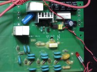
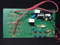
The most usual cause of failure in a multiplier HV supply is one or more of the caps becoming leaky or shorted.
Replace the caps. The values only need to be close, not exact.
It's a multiplier and the tolerances are fairly large. So if it uses a 0.003 you could put in 0.005 or 0.002 and be just fine... etc.
or if it has 0.03 the same... about -50% to +200% is ok, all the same is best. But in a pinch to test, anything will do.
Higher voltage parts are preferred.
The idea of swapping the HV boards is fine.
In my experience, measuring before the HV supply runs through a large value (megohm) resistor out to the panels, you can use a normal HV probe on any meter and go right up the multiplier ladder and see if the voltages are correct. Of course a shorted cap or leaky cap will pull the whole thing down from the first leg up to the HV output side...
Assuming your HV is ok (and that has not been determined yet).
the next thing to check is the input transformer's step up ratio and make sure it hasn't been fried by amp failures (DC across the primary or parasitic oscillations.
Check the DCR of the good unit primary and secondary vs the bad unit... make sure the HV supply is BLED DOWN TO ZERO volts and or disconnect the secondary from the panels... you don't want to discharge the HV stored on the panels through your ohmeter! 😀 They should be quite identical.
You could always unwire the interfaces, mark the panels & interfaces and swap them too... that would tell you instantly where the problem is... but I'd try the above tests first.
Any HV diode will work fine.
1N4007s are fine general purpose HV diodes... higher voltage diodes will likely not break down over time in the event of various variations in component values or spikes... as noted there is nil current being drawn so that almost doesn't matter.
_-_-bear
Be aware that the EHT board is fed with about 600vac from the mains transformer. The high voltage end is fizzy but safe, the low may give you a surprise. So take care.
An EHT probe into a normal DVM will suffice to measure the EHT, I have a 'Testec TT-HVP 40' which is good for 40kv and measures Quad ESL63 EHT boards to be roughly what is specified. http://www.testec.de/
There are probably many alternatives. I think you need to actually measure the EHT before moving on to other possible concerns.
Paul
Low eht voltage
Hello,
I have 25 years experience on QUAD electrostatic speakers ESL (called today ESL57) ESL63 usual and ESL63 PRO.
First thing to do is to disconnect the speaker from main voltage, pull the socks down then delete the rear grill , check the EHT voltage with an EHT volmeter (you will find the address on the one thing audio site in UK "onethingaudio.com"
IF the voltage is not good enough (5,3 KV) discharge the EHT line (orange wire to ground it through a resistor) and then disconnect every element one by one (discharge between each step) and check the EHT voltage under this condition. If the value still the same,try with the next one following the same procedure, this way you will find wich one cause the EHT voltage goes down. If nothing change and voltage do no go to higher value this is coming from the eht board itself.
Repair this board is really easy and loose his time to check component is not necessary. Change diodes and caps in once and everything will be in order .
Feel free to contact me if you need it.
PH
Question about ESL-63 EHT suply
I want to update ESL-63 to latest version. Can someone share information?
I need to know:
1. In the latest version of EHT power supply (with resistors 180K; 2х220К; 56K and one VDR) what is the value of VDR?
2. What is transformer secondary AC Voltage for EHT UNIT?
3. What is secondary AC voltage for CLAMP BOARD?
4. What kind of neon lamp is used in EHT? (voltage?)
Can someone share schematic for latest diode based clamp board and values of components?
Best Regards
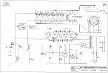
According to the Parts list posted for the ESL-2905 here: http://www.diyaudio.com/forums/plan...rvice-manual-quad-esl-2905-a.html#post44563731. In the latest version of EHT power supply (with resistors 180K; 2х220К; 56K and one VDR) what is the value of VDR?
- the VDR part number is S10K460
- R13 is now 100K, not 56K (this also agrees with the pics I pulled from ebay for an ESL-988 board)
See attached schematic of the ESL-2905 for the latest clamp circuit.Can someone share schematic for latest diode based clamp board and values of components?
- Zener diodes are type BZT03C-220
- Rectifier diodes are type GP02-30
Attachments

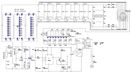
There's an error on the schematic above. The gate line going to the TRIAC does NOT attach to the LED and current limiting resistor. There's a connection dot that shouldn't be there I don't believe.
Some other notes, the 1000uF power supply cap is a 16v unit, and the power supplies run at 16 volts, sometimes more (at least on US line voltages). Replace them with 25V or higher units.
The TRIACS fail if the speaker has been badly overdriven. It still plays but like 40 dB quieter than it used to.
The triple stacked rectifier bridges with zeners still makes me scratch my head. Why not just one big bridge?
The new (988 and newer) board layout makes baby jesus weep. It's like they have no electrical engineers at quad anymore. It also makes me sad that the neon bulb can't be seen from the outside of the speaker anymore (there was an access port on the 63's).
Sheldon
quadesl.com
Arg! Thanks. There were several errors in the schematic from the 2905 service manual I had tried to fix. They had the orientation of diodes D28,29,32,33,36,37 backwards, no ground connection between HV and step-up transformer, R22A and R14 swapped, missing jumper wire on transformer...etc. Looks like I posted one of my earlier revision. Attached is the latest version I see on my HD. Let me know if you notice any other errors.There's an error on the schematic above. The gate line going to the TRIAC does NOT attach to the LED and current limiting resistor. There's a connection dot that shouldn't be there I don't believe.
I’m not sure…there were some earlier versions that did use a single bridge(schematic attached).The triple stacked rectifier bridges with zeners still makes me scratch my head. Why not just one big bridge?
Perhaps the thought was to avoid a direct short across the secondary if one of the bridge diodes failed.
But then why three bridges instead of two?

Attachments
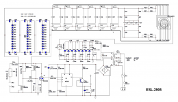
"The triple stacked rectifier bridges with zeners still makes me scratch my head. Why not just one big bridge? "
I guess it's because of the breakdown voltage of the diodes. They have a maximum voltage 3KV. If there is only one bridge, the tension becomes 6kV but it's pretty close to the voltage which pulls the transformer. And there are 3 bridges, diodes are 6, that would have passed 3 times higher voltage.
I guess it's because of the breakdown voltage of the diodes. They have a maximum voltage 3KV. If there is only one bridge, the tension becomes 6kV but it's pretty close to the voltage which pulls the transformer. And there are 3 bridges, diodes are 6, that would have passed 3 times higher voltage.
Last edited:

ESL63, there is no need to keep reposting... as an infrequent poster you are still under moderation and so all your posts have to be read and approved.
I have another one question. How much is transformer secondary AC voltage for EHT unit? I know it could be calculated backward but does anyone know the real value?
It's in the low 600 volt range, but I can't recall exactly. After the VDR and resistor bridge, it's about 500V AC.
WRT the three diode bridges. I hear what you are saying about exceeding the diode voltage, but you could series connect the same number of diodes and get the same overall breakdown voltage, but do it all in one big bridge rather than three stacked bridges. There's 12 diodes, which would make a 9000PIV bridge.
I also love the LED in the middle of the 7KV clamp. I replace it with a jumper in my boards.
A final comment, I love the TRIAC on the input, that's is a total "screw your amp" sort of a move on quad's part. The 220uf camp makes the input impedance damn near a dead short at audio frequencies when that TRIAC fires
Sheldon
quadesl.com
Last edited:
I've read that the secondary voltage of the transformer is 670V in ESL63 and 700V in the newer models. I have also read that the high voltage is 5.1kV and even 4.8kV - 4.9kV so I asked if anyone has measured.
I must admit that I have no adequate answer why they used three diode bridge not only one of the required amount diodes. I would have done with one. It is possible to miss something and the designer have had something in mind. If anyone knows let's say.
The construction with TRIAC is really dangerous for the amplifier but I think it is constructed with only thought to be as quick as possible to protect the panels instead amplifier.
And in older versions used not one but two triacs and a dinistor. This scheme also seems inadequate.

Hi All!
Can you tell me what are the wires that go to the stators and what goes to the frame in mylar?
I found a base and would like to use it to try out my self-built cells.
Thanks to everyone and ... Merry Christmas !!!
- Status
- Not open for further replies.
- Home
- Loudspeakers
- Planars & Exotics
- Parts for the Quad ESL 63