Hi hobby colleagues!
I have long planned to develop and assemble a multi-channel audio system based on fiber optic connections.
Now optical SFP modules are inexpensive.
I know electronics well, PCB in Eagle,
writing in C and Python language, including for microcontrollers. I know the DSP, but only in theory. Never wrote for FPGA.
Join the open-project, especially FPGA specialists are needed.
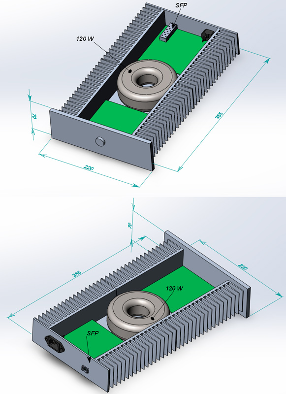
Mono module 60 W
I have long planned to develop and assemble a multi-channel audio system based on fiber optic connections.
Now optical SFP modules are inexpensive.
I know electronics well, PCB in Eagle,
writing in C and Python language, including for microcontrollers. I know the DSP, but only in theory. Never wrote for FPGA.
Join the open-project, especially FPGA specialists are needed.
Mono module 60 W
Last edited:
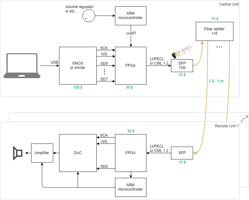
No PLL on remote devices will be used. The master clock is transmitted in the common TDM stream, the jitter of the SFP modules is very very small...
TOSLINK cannot transmit 8 channels 24 x 192 kbis/s x 8 ch = 36,864 Mbit/s
via SFP 1Gb, 200 such channels can be transmitted or over 60 channels 32x384 kbit/s
TOSLINK it's already yesterday.
SFP optics are much faster and cheaper, I wrote the prices in the figures
TDM frame for example

TOSLINK cannot transmit 8 channels 24 x 192 kbis/s x 8 ch = 36,864 Mbit/s
via SFP 1Gb, 200 such channels can be transmitted or over 60 channels 32x384 kbit/s
TOSLINK it's already yesterday.
SFP optics are much faster and cheaper, I wrote the prices in the figures
TDM frame for example
Last edited:


Thanks. IIUC the rate-select pin should switch the module to lower freq support, depending on params of the given module converter - SFP pin requirement - Electrical Engineering Stack Exchange
That jitter is comparable to decent SPDIF receiver https://statics.cirrus.com/pubs/whi...e_of_spdif_digital_interface_transceivers.pdf
That jitter is comparable to decent SPDIF receiver https://statics.cirrus.com/pubs/whi...e_of_spdif_digital_interface_transceivers.pdf
I indicated the above values jitter tolerance. For SFP is equal 0.2 UI
For TOSLINK 0.2 UI
real jitter SFP will be much smaller - about 10 ps
Jitter is inversely proportional to the maximum channel transfer rate !!!
SFP module can be set/read parameters via bus I2C...
For TOSLINK 0.2 UI
real jitter SFP will be much smaller - about 10 ps
Jitter is inversely proportional to the maximum channel transfer rate !!!
SFP module can be set/read parameters via bus I2C...
Last edited:
I see you using this image to represent jitter in your system:
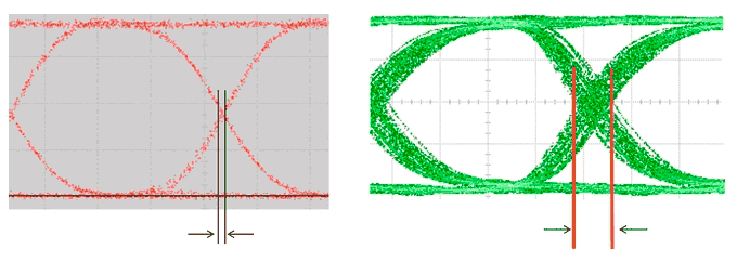
I assume this is supposed to be a digital signal, alternating between high and low? Only at the very bleeding edge of what sample rates can be supported would such "rounding" occur...
I really do not think that picture of jitter in a digital audio signal area really all that applicable to the "real" world, and if so they would only be a of concern where the digital audio is rendered via a DAC. This is under the assumption that the bandwidth of the signal transmission system is more than capable of carrying such a signal, and that the digital signal is not being bandlimited elsewhere. At what frequency do you expect to see such a pattern?
Would not a simple buffer and re-clocker at the DAC end of the chain make all of this a moot point ?
Hi, In that case you will need a PLL in order to recover the clock from the data stream.No PLL on remote devices will be used. The master clock is transmitted in the common TDM stream
I worked on optical telecommunication (PDH and SDH networks), and your idea seems realizable. What you want to realize is called time division multiplexing. In the TDM technology the individual data streams (for telephony they are 64kb/s) are multiplexed in E1 (T1 in the US) frames, 2048kb/s, and then E3 and up. For audio, you can start from E1, and multiplex 16 x E1 to get 34Mb/s, this will make 8 stereo channels. Or you can go higher, by multiplexing 4 x E3 to get an STM-1 (140Mb/s).
I don't think any error correction is necessary. You can use MMF (multi mode fiber) for domestic short distance use.
I am not sure about the SFPs support any bitrate. You can test a pair and then go further.
Are you planning this for studio use as a commercial product?
I can tell you that an audio CD playback chain has much similarities with telecommunications optical networking. There is laser, sliding window, PLL clock recovery, elastic buffer, jitter issues, etc. Most design and measuring techiques are common in both.
")
I'm sure the most critical factor in recovering an accurate clock from the incoming stream by FPGA is "continuous clock." SPDIF, which doesn't have "continuous clock," is commonly used in an audio application but not optimum for DSM, where low jitter clock is mandatory. That's why ESS has an internal ASRC for its SPDIF input. SPDIF has "burst clock" only at the preamble for clock recovery. I would say "burst clock" is old school technology mainly used in an analog system like old TV standard, NTSC and PAL. If you want to use FPGA for clock recovery and digital interface at the remote side, the continuous clock must be interwoven in a bitstream. "Burst clock" entirely isn't familiar with FPGA. If you can't have such bitstream, ASRC is the second option. My audio chain employs FPGA for clock recovery from the optical interface. Optical doesn't mean SPDIF(TOSLINK), but phase modulation, where the continuous clock easily can be interwoven.
Exactly. Here are some useful links about clock recovery from the E1 (HDB3 encoded) bit stream:
Clock recovery - Wikipedia
HDB3 - clock recovery???? | Electronics Forums
You need to calculate how many channels, what data rate and what bit depth can you transmit at 2048 kb/s. A mono 24 bit 192kHz signal is 4.608MHz in itself, that will not fit in E1. Probably you need to go higher and create your own specific frame structure. But then you will not be able to use any commercial chips, you will need to write the FPGA code yourself.
- Status
- This old topic is closed. If you want to reopen this topic, contact a moderator using the "Report Post" button.
- Home
- Source & Line
- PC Based
- optical SFP multichannel transport