OK, I've got a Boss DAC on its way for my Raspberry Pi w/ Moode. Now, what to do about a power supply?
I could simply purchase an iFi iPower 5V and be done with it. But you know, this being diyAudio and all, I had to look on the shelf and see what I could play with, so...
I have a beefy looking 12V 5A SMPS. What are the downsides of taking that 12VDC and putting a plain old LM338 after it to regulate down to 5VDC?
My RPi3 has a 5V 2.5A SMPS, so I think that SMPS with a 5A rated regulator IC should cover the current demand. But what are the other issues? Is the LM338 simply not going to reduce ripple enough? Will SMPS switching noise ride right on through the LM338 and its associated caps, etc?
I was thinking I could make a CRC filter from 10,000uF 25V--1.5R 10W--10,000uF 25V before the LM338 regulator. (Or maybe a choke like this one instead of the R?)
With a current draw of 2.5A I figure a voltage drop of 3.75V, which would leave 8.25V going to the LM338, leaving enough voltage drop to 5V to keep it from dropping out. That means a decent heatsink will be required for the LM338, but that's OK.
Is that just stupid?
--
I have a beefy looking 12V 5A SMPS. What are the downsides of taking that 12VDC and putting a plain old LM338 after it to regulate down to 5VDC?
--
Alot of heat through the regulator.
If the entire setup is mounted in an enclosure, it is likely to require for the heat to be vented.
With my RPi 3b and an audiophonics DAC being run from a 6v ouput (12v input), the wasted energy through the regulator gets things quite toasty. Thankfully i can run the Pi & DAC combo at slightly higher voltages.
A simple approach could be to wind a couple of turns around a ferrite. Best to use an oscilloscope to evaluate noise as an overly "treated" supply line can sound quite bad.
Last edited:
Alot of heat through the regulator.
If the entire setup is mounted in an enclosure, it is likely to require for the heat to be vented.
A CRC filter using a 1 ohm resistor could drop a couple volts and lighten the load on the LM338. I'm not too worried about heat. I'm kind of used to it, being from the vacuum tube end of things.
With my RPi 3b and an audiophonics DAC being run from a 6v ouput (12v input), the wasted energy through the regulator gets things quite toasty. Thankfully i can run the Pi & DAC combo at slightly higher voltages.
I have an RPi3 also. Does that mean it can run off of 6VDC? I wonder if the Boss DAC can run off of a 6VDC supply as well. That would be nice, since there are many ways to make a good linear 6VDC supply (used all the time for vacuum tube heater supplies).
--
Edit to add: The Raspberry Pi FAQs state that the max input voltage is 5.8V, or else the Pi and/or external USB devices may be damaged. I think I'll stick to a target of 5VDC.
Those same FAQs have a chart of expected current draw from the SBC.
For RPi3B (amps)
Boot
Max 0.75
Avg 0.35
Idle
Avg 0.30
Video playback (H.264)
Max 0.55
Avg 0.33
Stress
Max 1.34
Avg 0.85
I wonder how much current the Boss DAC draws? I guess it can't be more than 500mA, right? So I think 5V 2.5A is the design target for the PSU.
When people make linear supplies for these things, are they making really ambitious designs, or simple ones using LM350, LM338 or similar?
--
Last edited:
Hi Rongon,
I'm currently running the Pi and DAC at 7.9v (to minimise heat through the regulator). The the audiophonics dac, the power is fed to the DAC which has an onboard regulator (6-9v suggested) which inturn powers the Pi through the GPIO.
Please share how you go with the CRC filter. At a "guess", a 1.5v drop might be in the ballpark when its powered up ?
I tried to achieve something similar with a capcitance multiplier (using a TIP3055 transistor). The slight voltage drop helped a little bit with the heat. Not sufficient to run the regulator in a non vented enclosure.
Edit... with a 6v DC source, you could try running an zener + emitter follower. Use something faster and with higher gain than a TIP3055.
Something like this: http://www.tnt-audio.com/clinica/regulators_noise3_e.html
Without R13, R14, R17.
The TIP3055 was not fast enough when i gave it a go. The output voltage was not stable.
I'm using a switched mode power supply board (12v) - chunky ferrite - lots of X7R bypassing - LT1038 regulator. With a scope its "reasonably clean".
Yup, i'm with you. Cant see the DAC chewing up alot of current. I have not got my hands on a retail solution yet.
Last edited:
Re: CRC filter -- I'm totally guessing with this. I figure the current draw for a RPi3 with a Boss DAC HAT would be about 2A max, about 1A at idle? That would mean a 2.2 ohm resistor would be dropping 2.2V at idle, so that would need to be rated at least 5W (easy enough to get).
Starting from a 12VDC SMPS, that would drop to about 10VDC. From there it's -5V to the target 5V, which would mean the LM338 would be dropping -5V at up to 2A, which is 10 watts (!!). So yeah, that won't work well.
If I use a 4.7R 10W in the CRC, that should drop about 4.5V, so I'd be down at 7.5V DC at idle. Then the LM338 has to drop only -2.5V to get to the target 5VDC out. But what if the RPi draws its maximum 1.34A? That means the whole thing could draw a possible 2A (maybe). Now that 4.7R resistor drops 9V, and the LM338 drops out of regulation.
So yeah, this isn't easy at all. I think I'll need to take a 12.6VCT 4A transformer (I think I have one of those) and use a diode bridge to yield about 7.5VDC. Filter that with 10,000uF. That would feed the LM338, which would drop about 2.5V at Imax of 2A, for dissipation of 5W, which can be handled by a heatsink. The case it's in would definitely need vent holes, on bottom and on top.
LT1038 instead of LM338 looks like it would make a worthwhile improvement. But I already have a few LM338s I'd like to use up before buying more parts.
Or, I could buy an iFi iPower 5V ($49 + shipping) and be done with it.
--
Having tried various SMPSs and isolated PSs for my RPI's, I went down the Linear route, putting these together:
Toroidal Mains Transformer Dual Primary 115/230V 50VA 0-9V 0-9V Twin Secondary | eBay
A 5v variant of this:
Assembled S11 SUPER linear regulated power supply board LPS PSU L1511-10
Assembled into one of these:
1706 Full Aluminum Amplifier Enclosure/ Mini AMP Case/ Preamp Box/ PSU Chassis | eBay
I've connected both secondary 9v outputs in parallel feeding the LPS, taking 2 5v outputs feeding RPis.
I don't have an iFi Ipower against which to compare, but its a lot better than the SMPSs previously used, and I assembled it myself (which, at my age and with my eyesight, is a feat in itself!)
Actually, the max input voltage for Rpi3 is 6.5V. I use a 6V\8Ah Cyclon battery. This is the best I tried.The Raspberry Pi FAQs state that the max input voltage is 5.8V, or else the Pi and/or external USB devices may be damaged. I think I'll stick to a target of 5VDC
Actually, the max input voltage for Rpi3 is 6.5V. I use a 6V\8Ah Cyclon battery. This is the best I tried.
If you are feeding the mini USB you may get away with this, temporarily, if you are not using any accessories demanding extra current. If you are feeding the GPIO pins you want as close to 5v as you can get.
I could simply purchase an iFi iPower 5V and be done with it.
No. You're not.
There's space to make it an IMO real good supply.
But you know, this being diyAudio and all, I had to look on the shelf and see what I could play with, so...
If there are commercial quality products at very reasonable prices out there. I don't have any problems to go for them. Especially if I see no chance ( with DIY projects) to get close to its performance and price.
And you better make sure to understand what that supply will be used for.
I e.g. used a PS regulated with inmates MRAVLCA TPS7A4700 modules - as primary power stage followed by another ON-DEVICE regulated stage(s).
That didn't work well at all.
What I did then was removing the ON-DAC LDO replaced it with that TPS7A4700 and hooked it up to the iFi. That's been much better.
What I'm trying to say is that you shouldn't look just from the outside at your device.
If you want to do DIY then look at the entire supply chain for best results.
Good luck.
I just got an Allo Boss DAC HAT. It sounds great with the stock Canakit 5V SMPS. I've been reading posts from users who say that since the Boss DAC has extra power supply regulation onboard, supplying separately regulated DC to its digital and analog circuits, that it doesn't benefit as much from a brute force linear supply as other DAC HATs. One user claims very good results using an ungraded 5V 3A SMPS like this:
https://www.amazon.com/gp/product/B01N336XEU/
It's certainly cheap enough ($9 + s/h). He claimed that with an external USB drive connected to a Pi USB port, the drive would cause an error when used with the stock 5V DC SMPS, but with the above linked SMPS the drive worked fine. That suggests the above-linked psu is a step up from the stock supplies that come with a Pi. Unfortunately I can't find that post again.
The problem with regulating down to 5V from 12V is that 7V * 2A is 14W no matter how you slice it, and that's a lot of heat to dissipate safely.
--
You could use one of these, ask for the 6.3volt transformer for the max current.
K&K Audio | Other kits
K&K Audio | Other kits
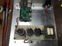
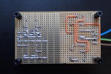
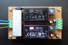
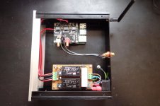
So here's my solution on vero board. The supply is based on 2 5V 2A Meanwell SMPS's each with a small filter on the output.
Using my dremel I removed all the unused traces on the mains side to minimise any arc over points or shorts.
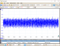
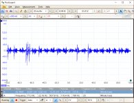
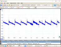
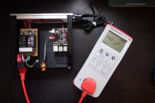
I measured the PSU rails without load and then connected to the RPi3 & BossDAC. As you can see from the traces the BossDAC with all its own filtering is fairly clean. The RPi3 generates quite a selection of noise depending on what it is doing. Most noise is seen during boot but then settles down once all the services are loaded. Both traces were taken while playing a FLAC.
Using my dremel I removed all the unused traces on the mains side to minimise any arc over points or shorts.
I measured the PSU rails without load and then connected to the RPi3 & BossDAC. As you can see from the traces the BossDAC with all its own filtering is fairly clean. The RPi3 generates quite a selection of noise depending on what it is doing. Most noise is seen during boot but then settles down once all the services are loaded. Both traces were taken while playing a FLAC.
Attachments
Last edited:
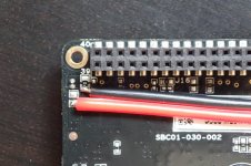
I'm not a fan of the small power connectors used on the BossDAC (J4) or the microUSB plug on the RPi. I think these can do as much to create power instability and noise as much as anything else especially at higher currents.
On the Boss I removed the link (0ohm resistor) on the top lefthand corner of the PCB to isolate the supply from the RPi. I then wired the Boss supply direct to the PCB as you can see in the pic.
The RPi is fed via the GPIO pins brought out on the Boss.
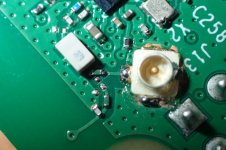
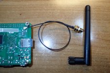
While I was at it I also modded the RPi so that I could mount an external antenna and house it all in a nice metal case. The components are soooo small so the result is not the pretiest but it works and I now have a connector for an external aerial.
On the Boss I removed the link (0ohm resistor) on the top lefthand corner of the PCB to isolate the supply from the RPi. I then wired the Boss supply direct to the PCB as you can see in the pic.
The RPi is fed via the GPIO pins brought out on the Boss.
While I was at it I also modded the RPi so that I could mount an external antenna and house it all in a nice metal case. The components are soooo small so the result is not the pretiest but it works and I now have a connector for an external aerial.
Attachments
Last edited:
Member
Joined 2009
Paid Member
Looks good!
How did you ensure proper safety earth given all the anodized pieces of the chassis but only one ground wire connection ?
Thanks.
Where the earth tag is bolted the screw has been countersunk on the other side and so has good bare metal to metal contact. On the ring tag side a serrated spring washer is used that provides bite between the two surfaces.
From there, but not ideal, I have relied on all the existing threads and screw points. They all meter good and pass a UK Class 1 PAT (portable appliance test) so I'm happy that all is safe.
Attachments
Last edited:
- Status
- This old topic is closed. If you want to reopen this topic, contact a moderator using the "Report Post" button.
- Home
- Source & Line
- PC Based
- PSU Upgrade Strategies for RasPi3 and Boss DAC --?