just the other night i was watching a movie and noticed that my aleph3 LED's kinda stay on when the amp is off.
they arent noticable during the day, but at night, its very dim and you can see them when they are off. can i just toss a small-value resistor across the leads to drain them down all the way? ive measured it, and there is just a very small voltage on them, enough to make them glow a tiny bit. it drains very slowly over time (like a half-day or something). would a resistor drain it quicker?
they arent noticable during the day, but at night, its very dim and you can see them when they are off. can i just toss a small-value resistor across the leads to drain them down all the way? ive measured it, and there is just a very small voltage on them, enough to make them glow a tiny bit. it drains very slowly over time (like a half-day or something). would a resistor drain it quicker?
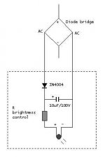
I've found a few ways I like to deal with that problem. One is to run the LED right from the AC from the transformer with its own diode, cap, and resistor so that it dies immediately after shutdown.
I suppose another way would be to use a transistor or a diode gate to turn the LED off when the power is switched.
These of course require slight modification to the original device.
Adding a resistor in to drain the LED is unlikely to be enough to drain it quickly unless it draws lots of current.
I suppose another way would be to use a transistor or a diode gate to turn the LED off when the power is switched.
These of course require slight modification to the original device.
Adding a resistor in to drain the LED is unlikely to be enough to drain it quickly unless it draws lots of current.
Tack a 1K resistor across the LED. If that makes the ON-state dim, try 2K.
I don't know the amp. But I'll guess that it is all MOSFETs. Say it runs a 50V supply voltage. When you turn it off, the active devices suck the power caps down. The caps are large, but not infinite: it will go down fairly quick, no more than minutes.
Except when it gets to about 5V, the MOSFETs turn OFF. Now only leakage flows. Good MOSFETs and good caps have low-low leakage. You could stall at 5V-4V for days.
The LED needs at least 1.6V to turn on, explodes at 1.7V-2V. You set brightness by setting current. 5mA to 20mA makes a nice glow. Since you have much more than 1.7V available, the simple way to set the current is with a series resistor. With 50V supply, 50V-1.7V= 48.3V across the resistor. 10mA is a nice glow: 48.3V/10mA= 4K7 resistor. Resistor heat is 48.3V*10mA, 1/2 Watt, you need a 1 Watt resistor. (This part was all done by the Designer.)
Now turn-off. Rail voltage falls to ~5V and stalls. The resistor sees 5V-1.5V= 3.5V, current is 3.5V/4K7= 0.7mA. A very dim glow, and some old LEDs would leak more than this, but yours apparently glows fine with 0.7mA.
Now add the 1K across the LED. It sucks 1.5V/1K= 1.5mA. If the rail voltage is stalled at 5V, it won't put enough current into the 4K7 to keep the LED voltage above 1.5V. It will turn completely off. In fact it can't turn-on if the rail is less than about 1.5V*(4K7/1K) or about 7V (actually 8.5V).
If the LED current was designed for 5mA (still bright in good LEDs, and less heat in the series resistor), then this 1.7mA bleeder will reduce brightness enough to notice. From 10mA to 8.5mA is probably not visible except side-by-side in matched LEDs, but 5mA to 3.3mA might be "dimmer". If objectionable, try 2K (2K2 is a standard value). Now the rail has to sag to 4.7V to fully extinguish the LED.
wow, thanks.
that helps a lot. its not a big deal, but its just kinda annoying that the light is barely on.
and yes, it is a mosfet amp, so i assumed it stopped playing when it got very low in voltage, and it has a 208,000uf supply per channel, so the little LED has a lot of power to feed from.
ill have to re-read your post to let it all sink in, but thats good info, and that will help me in the future for other things as well.
> it has a 208,000uf supply per channel
Yowsa.
Say the amp proper becomes an open-circuit below 10V.
Using my estimate of LED current, we have 0.2Farad(!) times 5,000Ω time constant: 16 minutes! At 16 minutes the rail voltage will be 3.7V, after 16 more minutes 1.37V.
Hmmmm.... that says that the LED should be dead-out after a half hour. I may have mis-guessed the LED current, so it might be an hour or even two. But probably not a "half day".
Big electrolytics have a lot of "soak". Short them to zero volts, let them sit open, the voltage creeps up again. Charge buried deep in the dielectric comes out slowly. But I don't see why that should allow any great extension of LED-linger.
I computed time-constant as if it was draining from 10V to zero. In fact it drains toward 1.5V, the LED threshold. So it may have a long linger around 1.5V. If we assume you can see (in dark) a current of 1% of "normal" current, we get 0.1mA. The slew-rate of 0.2F and 0.1mA is 0.000,5 volts per second. Assuming the LED passes roughly 0.1mA at voltages of 1.5V to 1.6V, a 0.1V spread, it would take 0.1/0.000,5= 200 seconds or 3 minutes. Is it possible you can see an LED with 0.01mA current? Seems unlikely; anyway that still gives ~30 minutes.
I'm baffled.
Three tricks:
AC-operated relay to short-out the darn LED when the power fails.
Give-away that 0.2F cap; 2,000uFd is all anybody really needs.
Duct Tape.
This is one of Nelson's boxes? See if he has a brilliant idea. ("PASS-Tape": looks like ordinary duct tape, but torn into 1"x1" squares and signed by Nelson Pass.)
> its not a big deal
Of course not. I'm just curious. I never saw such a long-linger. And if you have gone to some trouble to darken your movie-theater, a little red eye under the screen is going to stand out like a sore thumb.
Am I misunderstanding? Don't you just need bleeder resistors across your 208,000uf filter caps. 😕 Seems to easy, so I must have missed something??
What about a zener diode in series with the LED?
If you choose a value of B+/2 for the zener, you just have to wait for the MOSFETs to suck the caps half ways empty before the LED stops lighting...
If you choose a value of B+/2 for the zener, you just have to wait for the MOSFETs to suck the caps half ways empty before the LED stops lighting...
--Put the LED on the other leg of a DPDT power switch.
--Use a switch to disable some or all lights on the equipment when watching video. Flip the lights on for audio use.
--Don't use an LED at all. Use a light bulb. It will work all the way down to 0V.
...didn't we just go through all this for a preamp that played after the power switch was thrown? So much angst over such a...oh well...never mind...
You folks have fun.
Grey
there are a million ways to do what im asking.
i guess im just trying to learn electronics a little bit better. now that i kinda understand how bleeder resistors work, im trying to learn more about their applications, and other methods to do similar things. ultimately, im asking these questions so sometime down the road, i wont have to ask them, or if somene else asks them, i can fully answer.
i guess im just trying to learn electronics a little bit better. now that i kinda understand how bleeder resistors work, im trying to learn more about their applications, and other methods to do similar things. ultimately, im asking these questions so sometime down the road, i wont have to ask them, or if somene else asks them, i can fully answer.
> Don't you just need bleeder resistors across your 208,000uf filter caps.
That seems simple, and is. But as with most high-power bleeders, especially with oversized caps, the size/power/cost of the bleeder starts to get annoying. He already has a bleeder: the LED and resistor. That is too slow, he needs more bleed. I've guessed the LED bleeds about 5mA, and that the rail may be 50V, which is 0.25 watts, a comfy heat in a 1/2 resistor. If we need "more!", we are looking at 2 watt resistors for about 4X-6X shorter bleed-down, or 10W-20W resistors for pretty-quick bleeds (assuming this is a Power Amp that can take such added drain; as I said, I don't know an Aleph from an Omega).
> What about a zener diode in series with the LED?
That will work, with some issues to deal with.
Just adding a V/2 Zener will cut LED current in half. That may be fine, or you may want to resize the resistor.
Using a fixed voltage under a varying supply rail multiplies rail variation. If the utility company wobbles 10%, then the LED current wobbles 20%. That's probably not a big deal unless your utility power is awful.
> Don't use an LED at all. Use a light bulb.
Often not available in an appropriate voltage/current value for an amplifier.
Short life.
Possible DIY drawback: when it fails, you may think the amp is "dead" and stick your hand inside, when it is only the bulb that is dead, the power supply bites you. For DIY safety I much prefer long-life LED over sure-to-die incandescents (but I never really trust any indicator, they all lie sometimes).
> So much angst over such a...
If we were angst-free, we'd go down to BestBuys and find a good deal on a plastic music box. Plug and play. If it ever offends us, we put it in the garage and buy another. Hey, they're cheap!
Robert,
The bleeder resistor concept is easy to understand. All capacitors take a certain amount of time to charge or discharge depending on the load or resistance they have across them. We can calculate the time it takes to charge or discharge by 66% by using the formula R x C. This is known as time constant. If we had a 1 uF capacitor and a 1 meg resistor across it, it would take 1 second to charge to 66% of it's capacity or discharge 66% of it's charged capacity. The formula is calculated by (1000000 Ohms) x (.000001 Farads)=1 second. Say we put 10 volts across the capacitor in our example, it would take 1 second to charge to 6.6v (66% of it's fully charged value of 10 volts) or if the capacitor was fully charged to 10 volts and we removed the power in 1 second it would loose 66% of it's 10 volt charge and be at 3.4 volts. Ok, we discussed what happens after the first 1 second or time constant. In the next time constant it will charge or discharge to 66% of the voltage remaining. For example, after 1 second we charged to 6.6 volts leaving 3.4 volts more for a full charge. In the second time constant we will charge another 2.244 volts (3.4 volts x 66%). Now we can calculate the charge after 2 seconds or two time constants by adding the charge level after 1 second of 6.6v and the incremental charge of 2.24 voltage after 2 seconds getting 8.84 volts after 2 seconds. The same is true for discharging and the process will repeat until full charge or discharge is obtained. I hope this rather simplistic explanation helps.
The bleeder resistor concept is easy to understand. All capacitors take a certain amount of time to charge or discharge depending on the load or resistance they have across them. We can calculate the time it takes to charge or discharge by 66% by using the formula R x C. This is known as time constant. If we had a 1 uF capacitor and a 1 meg resistor across it, it would take 1 second to charge to 66% of it's capacity or discharge 66% of it's charged capacity. The formula is calculated by (1000000 Ohms) x (.000001 Farads)=1 second. Say we put 10 volts across the capacitor in our example, it would take 1 second to charge to 6.6v (66% of it's fully charged value of 10 volts) or if the capacitor was fully charged to 10 volts and we removed the power in 1 second it would loose 66% of it's 10 volt charge and be at 3.4 volts. Ok, we discussed what happens after the first 1 second or time constant. In the next time constant it will charge or discharge to 66% of the voltage remaining. For example, after 1 second we charged to 6.6 volts leaving 3.4 volts more for a full charge. In the second time constant we will charge another 2.244 volts (3.4 volts x 66%). Now we can calculate the charge after 2 seconds or two time constants by adding the charge level after 1 second of 6.6v and the incremental charge of 2.24 voltage after 2 seconds getting 8.84 volts after 2 seconds. The same is true for discharging and the process will repeat until full charge or discharge is obtained. I hope this rather simplistic explanation helps.
> 66%
63%.
1-(1/e)
Makes no practical difference to your explanation, or any real-world power-bleeder, but good to know if you work on precision timing systems.
63%.
1-(1/e)
Makes no practical difference to your explanation, or any real-world power-bleeder, but good to know if you work on precision timing systems.
Alright, alright....It's been over 25 years since I graduated college. I guess the old grey matter doesn't recall as well as it used to. 😉 😀
Hmm, why not ditch the led and use a 'mini' blue christmas lamp for a warmer, softer and more tubelike effect.😎 I think I'll do that on mine.
Hmm, why not ditch the led and use a 'mini' blue christmas lamp for a warmer, softer and more tubelike effect.
That will work but still will not solve his problem with it staying lit after removing power. He simply needs to bleed off the power supply caps.
Yes, my reasoning is that the lamp will draw more current than an led and be part of the resistance to drain the caps.
Ok, I see your reasoning. If I recall he has a large toroidal in his preamp so that may work well for him if he picked a lamp with a low filament resistance.
- Status
- Not open for further replies.
- Home
- Amplifiers
- Pass Labs
- bleeder resistor for front panel LED?