A few months ago, thanks to another audio forum, I started to consider looking at a solid state amp to see how I might prefer or not prefer it compared to small SET 45 amp. At the time, doing a diy project wasn't even on my radar and I was looking at what I could just buy, since I had never done anything like this before with electronics. I do have a pretty solid background building but strictly mechanical. Anyway, fast forward and somehow I started reading about these weird looking (fugly?) amps called First Watt or Pass or whatever. Long story short, that led me here.
For a solid month I considered, somewhat not seriously, building one as it was still a little expensive all things considered and there were so many things to buy that I didn"t have. As is usually said, and it is absolutely true, I cannot thank 6L6 enough for his guide and willingness to spend some time talking me through things on the phone before I committed to do anything. Thanks, Jim!
Anyway, my intent with this post is to list a complete newby's lessons learned that can hopefully help someone else. Here they are in no specific order.
Other than that I had a pretty uneventful build. Only one component needed to be desoldered and everything biased up perfect and offset to nothing. No hum, no loud turn on/off thumps, sounds great. Only bad news about the whole thing is the extra power the Aleph J provides makes some preamp hum a little more audible...new problem to solve.
With that, a few pictures 🙂
In order of appearance
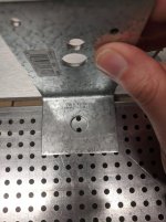
1. Simpson A24 bracket to mount toroid vertical
2. MOSFET Matching on the breadboard. Pot out of frame on the leads.
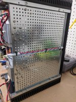
3. Routing under floor with notched edges and chaffing protection.
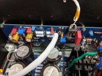
4. Euroblocks for inputs and 13 AWG that didnt really fit in outputs.
5. Sneaky routing from PSU to amps behind the boards and ground.
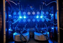
6. Glamour Shot 🙂
edit: almost forgot, full build album here
For a solid month I considered, somewhat not seriously, building one as it was still a little expensive all things considered and there were so many things to buy that I didn"t have. As is usually said, and it is absolutely true, I cannot thank 6L6 enough for his guide and willingness to spend some time talking me through things on the phone before I committed to do anything. Thanks, Jim!
Anyway, my intent with this post is to list a complete newby's lessons learned that can hopefully help someone else. Here they are in no specific order.
- Review the schematic while following the build guide. This would have saved removal of a couple of incorrect parts on the PCB.
- Review the schematic while looking at any BOM & Build Guide. As it ended up, I had an old BOM revision that was wrong on the diyaudiostore page for the Aleph J. I ended up ordering a couple of wrong parts and completely unneeded parts. If someone knows anyone there, maybe you can get them to update to the latest included in the build guide thread.
- Use good name brand solder, e.g. kester. Bought some stuff with my soldering iron that came from china that was like putty when "molten". Thankfully I figured this out long before I got near a PCB with this garbage.
- Flux is your friend and it really helps on some of the larger solder pads.
- Cleanup solder flux as you go and don't wait till the end. Sidenote, don't try to build one during a pandemic when trying to find 90+% IPA is basically impossible. Hah! Just my luck.
- The 4U chassis is definitely at its capacity with 2 PSUs and 2 toroids. Keep this in mind when planning the project. The difficulty is less about fitting everything in, but fitting things in AND putting together the "Deluxe" chassis. As it is I had to drill through the faceplate to make it work.
- As you read through threads, download any and all picture that might be remotely useful or serve as inspiration for routing wires, options for mounting components, etc etc.
- Read the threads and ask for help before you need it. This can be a hard one because they are so massive in general and you may not know your next problem.
- Matching MOSFETs is pretty straight forward but does require a few things that a "regular person" who hasn't done this before may not have. (breadboard picture)
- In addition to double checking every resistor value BEFORE installing also double check and verify continuity of everything AFTER installing. So quick and easy to do.
- Get some good binocular loupe magnifiers for inspecting solder joints.
- Use a bulb tester but don't freak out when the bulb stays lit when hooked up to the amp boards with a 100W bulb. The mosfets are hungry.
- Routing mains under the floorpan like is shown in many builds requires extra spacers or notching the bent down edge like I did. (picture below)
- The same euroblocks that can be used on the PSU can also be used on the amp boards for inputs. Nice! Had 2 extra since I ordered 10 for a qty discount that found a nice home on my amp boards. Highly recommend.
- Vertical mounting of the transformers with a full PSU is pretty much required unless one uses risers. Toroid has an L-300 but they didn't get back to me. Have also seen some other things people have retrofitted, but I found some really great angles that I'd recommend. They even sort of already fit with the hole pattern in the floor. Simpson A24 2x3.875"angle. Simpson A24 2" x 3-7/8" Angle - G90 Galvanized
- 14 AWG stranded is about as big as will fit into the amp board's output.
- Mouser is great to work with. Obviously your experience may vary, but I screwed up an order, called them, and they helped me out so quickly AND were able to give me free shipping.
- Buy good tools (duh) and don't skimp on a nice stripper especially for stubborn/tough insulation like on PTFE wires and the Antek primary leads.
- Plan out wiring as you build and don't wait till the end especially for tight builds. Would have made my life much easier to solder the +V/-V/G to the amp boards before I started to hookup PSU's.
- Chase threads on the heatsinks before you end up binding a standoff and having it shear off. Speaking as a mechanical engineer, many of the tapped threads on my heatsinks were poorly finished.
Other than that I had a pretty uneventful build. Only one component needed to be desoldered and everything biased up perfect and offset to nothing. No hum, no loud turn on/off thumps, sounds great. Only bad news about the whole thing is the extra power the Aleph J provides makes some preamp hum a little more audible...new problem to solve.
With that, a few pictures 🙂
In order of appearance
1. Simpson A24 bracket to mount toroid vertical
2. MOSFET Matching on the breadboard. Pot out of frame on the leads.
3. Routing under floor with notched edges and chaffing protection.
4. Euroblocks for inputs and 13 AWG that didnt really fit in outputs.
5. Sneaky routing from PSU to amps behind the boards and ground.
6. Glamour Shot 🙂
edit: almost forgot, full build album here
Attachments


Last edited:
Fantastic! Great advice for everyone.
I never noticed that the Euroblocks fit on the amp boards. Excellent!
I love the clean / tight wiring. Using yours as an example, I should be flogged for my builds. Of note, I neglected to protect my mains wiring with some nice shrink-wrap or other material around the edges of the perforated plate bottom plate. I'm stealing that. It'll add some peace of mind.
Congratulations on the build, and thanks for sharing your experience and tips. 😀 😀 😀

Simpson bracket is a good one! And euroblocks on the inputs... uh why didn't I think of that!? And you took on mosfet matching... GREAT!
always good to see a methodical approach to a successful build.
congrats and enjoy the aural delights it will bring.
..dB
congrats and enjoy the aural delights it will bring.
..dB
Thanks for the kind words, everyone!
I was really nervous about this whole thing; circuits and my other EE type courses in school were not my best. This was as much about building something for me as it was to start to face my demons, if you will 😉. Have always had a "might as well jump in if you're going to get wet" mentality about hobbies and projects.
I'll note that this thread tried to be as generic as possible, but the Euroblock tip comment I made, it might apply to other amp boards, but uncertain. It definitely worked on the AJ. Also not sure I can take full credit for that, I think someone in the AJ build thread did that and I saved off his picture without realizing that at the time. Saw that later and thought it was a great idea.
From another Mechanical Engineer who somehow got into this EE's hobby (sounds like that's the case anyway)...Very nice build sir! Great job for your first time! I'm also using an Lifetime table for a workbench right now...and I have Darn Tough socks! Ha!
I just recently built a DBT in the same format as yours for testing another project. And I got that same duplex/toggle cover plate for the box but for some reason when I try to mount the plate, it sits 1/2 above the switch and receptacle. Did I use the wrong box the wrong cover? Or am I doing something else wrong?
Cheers, and happy Friday!

From another Mechanical Engineer who somehow got into this EE's hobby (sounds like that's the case anyway)...Very nice build sir! Great job for your first time! I'm also using an Lifetime table for a workbench right now...and I have Darn Tough socks! Ha!
I just recently built a DBT in the same format as yours for testing another project. And I got that same duplex/toggle cover plate for the box but for some reason when I try to mount the plate, it sits 1/2 above the switch and receptacle. Did I use the wrong box the wrong cover? Or am I doing something else wrong?
Cheers, and happy Friday!
On the bulb tester I had to bend off a couple of ears so the switch/outlet would sit flush to the face plate. Should see some obvious scoring lines similar to the tab you'll likely need to break off on neutral/wide leg side of your double outlet to keep the live wire going into the bulb socket from shorting to the neutral you'll wire on the current limited socket. I think I also had to bend the top of the switch a little bit to clear or maybe it's that I had to bend it back after bending off the ears? Either way, approach the problem like a Mechanical Engineer,
i.e. Bigger hammer 😀
Also, great eyes on the socks! I dont even remember my feet being in the pictures. haha!
Fugly!
(even if I really hate these automotive wire connectors)
if you're talking about those big yellow spades....i know, tell me about. I dont like them either, but it's what i had. I really should have waited to get something better but oh well. The nice spades I bought didnt fit the speaker output/ground cable. Really wanted to use this since it's the same speaker cable I use outside the amp.
Last edited:
If anything helps you at all that makes me happy. Good luck on the build and have fun.
Perhaps one tip i should have mentioned is to work in bite size pieces. For some people making a list of the immediate next tasks to do will help as things become more "free form" when getting to hooking up everything, routing wires, doing checkouts, soldering connections, etc.
Everything otherwise is mostly "paint by numbers" with respect to stuffing the boards.
Maybe you can help me with something else. I bought the PS board, but I haven't purchased the components for it. I've seen a few different BOMs in the threads, and lots of suggestions for modifications, improvements, different caps, etc. I'm totally lost in that area. Can you recommend one, simple, non-outdated BOM that i should just use to buy everything and be done with it? I don't know enough to evaluate various tweaks and upgrade options. Thanks.
I suppose the same point applies to the Aleph J amp itself. I did get the JFETs and MOSFETs, but that's it.
Maybe you can help me with something else. I bought the PS board, but I haven't purchased the components for it. I've seen a few different BOMs in the threads, and lots of suggestions for modifications, improvements, different caps, etc. I'm totally lost in that area. Can you recommend one, simple, non-outdated BOM that i should just use to buy everything and be done with it? I don't know enough to evaluate various tweaks and upgrade options. Thanks.
The short answer is that it depends. Are you going to use the diode rectification or use monolithic bridges? What transformer are you planning to use?
In it's simplest form, all you need are 8 capacitors and 8 resistors for the CRC. Those are capacitors of at least 35V/85°C/15000uF/10mm Leads/35mm diameter or smaller and 3W .47 ohm resistors. I would recommend buying capacitors with 50V and 105°C rating just to have a little extra life and margin. Was worth the extra dollar per capacitor to me. It is highly recommended/semi-mandatory to also use a bleeder resistor to make sure you capacitors get drained after power off. Use another 3W resistor, 5k to 22k I believe is the recommendation. The LED's are nice to give verification that it's powered and there's energy stored. You'll need another resistor to adjust voltage going into the LED. I think I used 5k's. I really like the euro blocks for routing the DC output to the amp boards and also really like the spade connectors/blades for the transformer secondaries. Neither are strictly needed as you can solder the wires directly to the board, but I'd personally recommend using them.
With the rectification diodes, you'll need 8 FEP30DP diodes, the matching heat sinks, thermal grease/mica/other insulators, and the fasteners needed to join them.
The real potential rabbit hole is the input snubber. If you're lucky enough, your transformer will be listed in the quasimodo thread here. If it isnt, I'd still recommend doing it, hopefully using the thread as a guide. Use the capacitors they recommend. The trick is the resistor. I made a guess at what I needed with a slight bias to overdamp the snubber. Seemed to make sense to me that it wasnt important to have a perfect critically damped snubber since this is a non-switching power supply. There were some articles linked in the thread that argued the same thing. Don't bother with anything labeled output snubber next to the euroblock outputs.
Overall, I used the BOM on the diystore and referenced the illustrated build guide. The PSU is very straight forward. Also keep in mind you will need one CL-60 thermistor, or equivalent, to lift the PSU ground off the chassis by a little bit to have a nice quiet output/avoid ground loops.
I suppose the same point applies to the Aleph J amp itself. I did get the JFETs and MOSFETs, but that's it.
Use the aleph bom that is linked on the illustrated build thread by 6L6. DO NOT use the one on the diyaudio store. It's old and out dated. Since I had the bad luck of using the old one, I can't comment on everything in the new BOM, but I would print it out and go through the schematic and 6L6's build guide and verify that it matches what he's doing with respect to all the jumper locations and the 1k resistor that should be in R8. Otherwise, the aleph boards are pretty straight forward. Look at the schematic and bom and build guide and make sure all 3 things agree. If they dont, double check and ask why. I also really like the euroblocks on the input as it made it very easy to hookup the signal input. Keep in mind you'll need to jumper Ground to -IN for RCA's.
The only other "trick" is to make sure you have the matching IRFP240's paired up. Also a good idea to ziptie/heatshrink the JFETs together to have them operate at the same temperature.
6L6's build guide is really fantastic for more help. Next time I might have increased the height of the big 3W resistors to make measurement easier during biasing. Not a big deal though.
Hopefully that helps. If you want, feel free to message me and we can chat more there.
Last edited:
Just curious why you decided to go to with two transformers and two PSUs for the Aleph. Do you have reason to believe that you will get better performance than a single 500VA 18v/18v transformer and PSU?
Fair question. A handful of reasons;
First, Antek was out of stock of all the usual suspects when I was order, so no 3218/4218 and I didnt want to go bigger than that. I realize now I could have been just fine with a 3220, which i think was in stock at the time, but being a first ever build I was irrationally worried of not using the 18V secondaries thinking that it might cause me some issues biasing up.
Second, as you mentioned, I thought there might be some gains to be had with separate PSU's after reading of a few other folks who started with a single PSU and then added a 2nd.
Third, when I asked for advice from 6L6, he noticed I was buying capacitors in quantities of 10 to get the quantity discount. He then made the suggestion I should just buy 16 to have enough for a 2nd PSU build later on...cause no one builds just one. Thought that was a reasonable suggestion.
Fourth, having the full set of caps for 2 psu's that would be entirely matched, if that makes any difference, it would be very straightforward to build another amp, buy another chassis, find a couple of DPDT switches, and have switchable monoblocks.
Fifth, because given the current pandemic and staying at home, I need some method of exercise....boy is this thing heavy. haha!
- Home
- Amplifiers
- Pass Labs
- New Aleph J Born & Newby's Tips