Ahh, different notation on the Chinese version of these boards. It appears that V- is used to indicate power supply ground, and GND is used for audio input and speaker output ground. Yes, it's a bit strange. Try a continuity test between V- and GND to confirm a connection.
The ACA is fundamentally a single rail design. Check out the schematic that I posted a while back. It still applies to the ACA #1, but includes R15, which Mr Pass originally intended to be part of the circuit.
The ACA is fundamentally a single rail design. Check out the schematic that I posted a while back. It still applies to the ACA #1, but includes R15, which Mr Pass originally intended to be part of the circuit.
Ahh, so it is a single rail, I'll get my DMM out and check as you suggest.
Well, that makes things a bit simpler then, I have suitable single rail supplies I built a while back I could use. Perhaps this one, using two L7818s will do, it can output 1.5A per rail, I built two identical supplies on the one piece of veroboard using the schematic from the L78xx datasheet with the addition of a few extra 2200uF smoothing caps. 18x1.5=27W, which sounds sufficient to me. If not, I can get some beefier regulators and soon knock up a pair of similar supplies that will handle more current.
I've unsoldered the MOSFETs and ordered four IRFP240s, let's do this right. The two 2Sk170s on the BOZ are perfectly matched with IDSS of 9.9 as are the two 2SK170s on my ACAs - I ought them from a forum member as a matched quad, so might as well use the right MOSFETs as well, instead of cutting corners.
Attachments
Last edited:
I see the R15 addition, looks like a simple mod, just solder a 2.2k resistor across two of the 3w resistors. I happen to have some Neohm LR1 0.6w metal film resistors in 2.2k, would that do the job?
Yes, the 2.2k resistor you mention would be fine for the R15 addition. However, you need to make sure it is connected between the Drain of Q1 and the Base of Q3. These points would also correspond to one end of the 0.68 Ohm resistors and one end of R8. Best to verify proper connections with your DMM.
The addition of R15 will help the amp sound more lively and dynamic, as it was intended. It will also increase the quiescent current through Q1 and Q2 to about 1.4 Amps. I have confirmed this current with my boards. So you will need to plan your heat dissipation accordingly.
The latest pictures of your LM7818 based regulator boards show an unsafe use of a bridge rectifier that will be dangerous to use with a Class A amplifier. While the 4-pin bridge may be rated for "1 Amp", it will literally burn up under a continuous 1 Amp current draw. We would both hate to see your nice vintage Sharp chassis damaged.
There are other issues with those regulator boards as they are currently assembled. Rather than list a set of steps that might be taken to salvage them, I would like to repeat my recommendation to use one of the Mean Well SMPS bricks. I provided the part number for the 24V version earlier. If you would prefer to run your boards at 20V instead to help with power management, then the preferred part would be a GST120A20-P1M.
I see the R15 addition, looks like a simple mod, just solder a 2.2k resistor across two of the 3w resistors. I happen to have some Neohm LR1 0.6w metal film resistors in 2.2k, would that do the job?
Thanks for the info, I'll consult again before actually soldering on the R15.
I built those PSUs for a DAC build, so yeah, they aren't built for high current and as you suggest, I'll sideline them and do something else.
I'll take a look at the Meanwell, thanks for the tip.
I've reworked the Sharp chassis quite drastically to make it suitable for a Class A installation. The pressed steel rear panel and a couple of other steel pieces have been removed, as has the pressboard base. These will be replaced by a single piece of aluminium 400x300mm and 4mm thick, bent into an L shape. External heatsinks will be bolted to this plate so they stick out he back of the amp. The ACA boards will be bolted to this plate too, so there should be more than ample volume of aluminium to soak up the heat and radiate it again. I'll take pics of my reworked chassis soon.
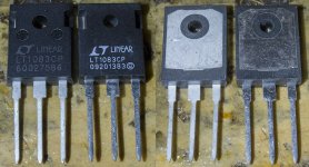
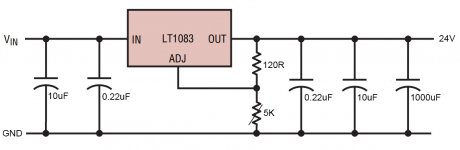
Rooting in my parts pile I found I have a pair of LT1083CP regulators in TO-247 package, these will handle upto 30V at 7.5A, the basic circuit is very simple and I have all the parts needed:

If I understand correctly, the output voltage is set by the variable resistor, I want 24V output so does the fixed 121ohm value and the 365ohm variable value remain the same for 24V or do the values need to be adjusted? The variable resistors I already have are 5K, so I'll have to get some more, just checking what value to get. The fixed resistor, should that be a 3W type to handle the current flow? Wirewound or metal or does it not matter?
In 3w I have 110ohm carbon and 150ohm metal oxide, would either of those do in lieu of 121ohm?
Can I replace the variable with a fixed calculated to the right value to give a fixed 24v output?
I also found a pair of square metal rectifier bridges that are good for this use as they are the bolt to a sheet of metal type and will handle 25A of current at 400V.
Last edited:
Yes, that LM1083 is a good regulator for this application. The variable resistor in the diagram needs to be a 5k part to give enough adjustment to get 24V on the output. (The 365 value is for 5V out.) The fixed 121 Ohm resistor can be 1/4W.
For a high current application, you will need 10,000 uF or more on the input of the regulator. I would go with a pair of 6800uF, 35V or 50V caps in parallel. The output just needs 47uF or so to ensure stability, but you can experiment with higher values up to 470 or 1000uF.
The 25A, 400V square metal bridge rectifiers are the way to go.
I am building 24V preamp supplies using Pete Millett 5V filament reg boards. I asked Pete what to change to go from 5 to 24V. Board is using a 1084 but I think pinout is the same. You may use his suggestions for values. They are here:
*************
To keep power dissipation in limits, you should change R3 to 270 ohms. R1 + R2 would then need to be about 5k. You could make R2 4.7k and R1 (the pot) 1k. R4 should also be 5-10k.
You need to use caps with a high enough voltage rating, the biggest that fits is good, probably 2200uF 50V on the input and 100uF 35V on the output.
*************
You can go to Pete Millett home page to see the schematic and what is R3 etc. Pete board has 3 input caps…..so 3 x 2200 uF 50V I use…..
*************
To keep power dissipation in limits, you should change R3 to 270 ohms. R1 + R2 would then need to be about 5k. You could make R2 4.7k and R1 (the pot) 1k. R4 should also be 5-10k.
You need to use caps with a high enough voltage rating, the biggest that fits is good, probably 2200uF 50V on the input and 100uF 35V on the output.
*************
You can go to Pete Millett home page to see the schematic and what is R3 etc. Pete board has 3 input caps…..so 3 x 2200 uF 50V I use…..
I only need small current for preamp use…..< 1A so for me 3 x 2200 uF after the bridge should be fine......you should probably go for more.
Thankyou for the guidance, you are saving me a lot of trial and error and wasted effort, so it's warmly appreciated.
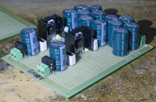
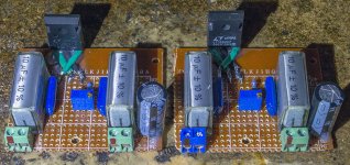
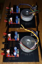
Camera battery is charging, so no pics yet, but what I've done is built too identical regulated supplies using the LT1083s, the boards are about the same size as the ACA boards and I plan to bolt them to the heatsink alongside the ACAs so the wire runs for the power are really short.
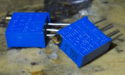
I used the reference design from the datasheet but added a pair of Konek MKT 0.22uF 250V caps in parallel with the RIFA 10uF poly caps, with the smaller ones closest to the regulator, and also added a Rubycon YK series 1000uF 50v cap just before the output for stability. I haven't soldered on the 5k adjustable pots yet, not sure how to connect the three pins they have, so any guidance on that would be very helpful, it's the last step to complete the regulator boards.

Smoothing caps to go before the regulator board input is taken care of too with a pair of cap banks I built a while ago that have 50,000uF comprised of 107x 470uF 50V Nippon Chemicon caps in a tightly packed array.
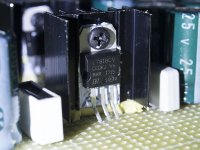
The LT1083s I have are different, one came from a UK supplier and is surely genuine, the other came from China at a fifth the price and is probably fake as it has silkscreened lettering rather than laser etched and the metal of the legs is much softer and easily bent, so I may need to replace the 'fake' Chinese one, it will be informative to try them both and see how they perform in comparison. 1.4A current through a 7.5A rated part shouldn't be too taxing for the Chinese one I hope.
Real one is on the left.

The Millett circuit sounds interesting, I shall check that out. I am very open to changing the PSUs at a later time as it would tech me a lot about how different types affect SQ.
Camera battery is charging, so no pics yet, but what I've done is built too identical regulated supplies using the LT1083s, the boards are about the same size as the ACA boards and I plan to bolt them to the heatsink alongside the ACAs so the wire runs for the power are really short.
I used the reference design from the datasheet but added a pair of Konek MKT 0.22uF 250V caps in parallel with the RIFA 10uF poly caps, with the smaller ones closest to the regulator, and also added a Rubycon YK series 1000uF 50v cap just before the output for stability. I haven't soldered on the 5k adjustable pots yet, not sure how to connect the three pins they have, so any guidance on that would be very helpful, it's the last step to complete the regulator boards.
Smoothing caps to go before the regulator board input is taken care of too with a pair of cap banks I built a while ago that have 50,000uF comprised of 107x 470uF 50V Nippon Chemicon caps in a tightly packed array.
The LT1083s I have are different, one came from a UK supplier and is surely genuine, the other came from China at a fifth the price and is probably fake as it has silkscreened lettering rather than laser etched and the metal of the legs is much softer and easily bent, so I may need to replace the 'fake' Chinese one, it will be informative to try them both and see how they perform in comparison. 1.4A current through a 7.5A rated part shouldn't be too taxing for the Chinese one I hope.
Real one is on the left.
The Millett circuit sounds interesting, I shall check that out. I am very open to changing the PSUs at a later time as it would tech me a lot about how different types affect SQ.
Attachments
Last edited:
The Pete Millett schematic and PCB is here:
Regulated DC filament supply
….then it should be easy to adapt to the new values for 24V output.
For the 5k pots.....I think it is written on it which pin is what…..1,2 and 3. The center pin no. 2 is probably the one which travels up and down. If you use an ohm-meter it is easy to find out. The CW symbol is used to define the orientation so turning Clockwise the resistance will increase from pin 1 to 2. Something like that…… 🙂
Cheers, I will study the Millet design and may indeed upgrade my supplies using it at a later date. Or sooner if I run into problems with the supplies I just built.
I installed the pots as rheostats with pin 1 being the input and pin 2 (the wiper) the output to earth, leaving pin 3 unconnected. I think this is correct.
My two regulator boards are now finished, I'm just waiting on the MOSFETs to arrive to finish the ACAs, so it's largely a matter of building the chassis up now then installing the parts and wiring them up right.
Last edited:
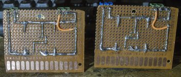
Some pics of the two LT1083 reg boards I've built, not my neatest work but should do the job okay:
Attachments
Last edited:
Schematic from Pete has pin 1 and 2 connected together to Gnd and pin 3 (CW) connected to the "circuit".
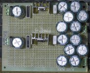
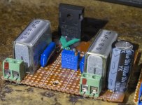
The picture shows how far I am in the moment with my two 2 x 24V supplies based on Pete's PCB. They are for the BA3-pre which will be used for both MoFo and ACA. Later I will build the NuTube pre which will be intended for the ACA.
The picture shows how far I am in the moment with my two 2 x 24V supplies based on Pete's PCB. They are for the BA3-pre which will be used for both MoFo and ACA. Later I will build the NuTube pre which will be intended for the ACA.
Attachments
These supplies are to be used for low current only (< 1A). So for e.g. preamp use. It is nice they can be used for many projects. I have become fan of having the PSU in its own chassis so all the "magnetic" noise has a little distance to the amp itself. The wire length from PSU to amp should be limited in order not to introduce other problems.
- Status
- Not open for further replies.
- Home
- Amplifiers
- Pass Labs
- Amp Camp #1