Say for something like the BA2: LTP input stage followed by single-ended VAS. How does one choose the current to give the VAS stage?
there is adequate calculus , which includes input capacitances and input impedances .... taking rise time in account as main thing ..... but I used it so long ago , that I simply forgot it
always used rule of thumb in meantime , later resorted to thumb of rule ...... just crank it 🙂
always used rule of thumb in meantime , later resorted to thumb of rule ...... just crank it 🙂
Generally it wants much-more than the drive requirement of the Output stage (which you did not mention).
Thanks for that link, Itsmee. Now I understand PRR's question, as it appears the answer has much more to do with what the VAS is driving than with the VAS itself.
The output stage in the example is a 4-pair BA2, which I think was one of its original incarnations (though the current one is 6-pairs). So the BA2 number is certainly relevant.
The article suggests I want as much current as possible to counteract the common source inductance and the Miller effect charging the capacitance of the gate. Is there a downside to supplying more current?
No but everything is a compromise, you just have to pick and choose which ones you want.
Depends on how far you go, main one is heat, component dissipation, geting rid of it, powering it in the first place - bigger psu...
Depends on how far you go, main one is heat, component dissipation, geting rid of it, powering it in the first place - bigger psu...
Sorry for jacking your thread...
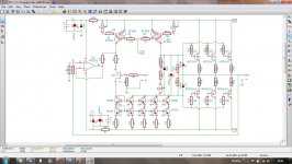
This is a couple of ideas I've been kicking around for a while, haven't gotten round to trying them yet, it's in the queue - too many project, they might not work.
Preserving the jfet gain is a trade off in reduced drive, seems to me that the best way would be to use a current mirror; the first leg monitors the JFET current, the second leg replicates the first leg (no load to drag it down), legs A, B, C are copies (current multiplier). Only Q7 & Q8,A,B,C need to be mached.
If you look at the normal LTP, the feedback JFET is only used as a sorce follower, seems to be a bit of a waste; a unity gain non inverting opamp could do that, it's only going to see a volt or two.
It shouldn't change the sound too much.
EDIT think i need to flip opamp to inverting???
Attachments
Last edited:
Can't you get the current mirror to multiply the current just by varying the resistance between the first leg and the second? Why do you need the other legs?
For what it's worth, I think the HPA-1 uses a current mirror in a similar fashion, only with a complementary (F5-ish) front-end and current mirrors on both sides. (It also uses an op-amp, but as a DC servo. The feedback mechanism is F5-ish.)
For what it's worth, I think the HPA-1 uses a current mirror in a similar fashion, only with a complementary (F5-ish) front-end and current mirrors on both sides. (It also uses an op-amp, but as a DC servo. The feedback mechanism is F5-ish.)
Can't you get the current mirror to multiply the current...
Yes, most people do it that way, if you do, to me it's not a true mirror, the transistors aren't operating at the same point.
...It also uses an op-amp, but as a DC servo...
Isn't that what the feedback jfet's job is? or did I misunderstand.
I'm looking for general guidelines.
Answered.
But let's use this for an example
First specific: this drives MOSFETs. The gate drive current is about zero at DC and quite high at higher frequencies due to gate capacitance. So you need to quantify that _and_ decide how high freq you need to go.
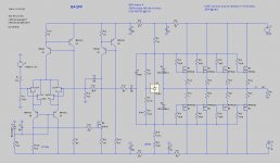
I don't know who drew this or if I am stepping on toes, but I got my boots on....
"LPT trim" seems unnecessary. A current-mirror will force input current balance. That may cause a voltage offset (MOSFETs are so inconsistent) but this can be trimmed while maintaining the more-important current balance. Also the R110 approach assures asymmetric limiting to M9 while a mirror has hope of symmetry (as D.Self(?) shows, not always that simple).
Since input is small-signal and the "VAS" is "medium signal" it seems odd to find 33mA in the input and 5mA in the VAS. If the output was some teeny thing... no, there's 130pFd Gate-Drain, so 1,000pFd loading at least. Counting on my belly-button, isn't all the drive current used-up for full power at 16KHz? While we may never see that in speech/music, we like a lot more headroom, if we can afford it, and I think this can.
Not even going to comment on having a potentially good gain-amp and then omitting all extra NFB around a bunch of ugly output MOSFETs, because I suppose that is a matter of taste.
good book for things like this is Valve Amplifiers by Morgan Jones
glass or sand , things are simillar
glass or sand , things are simillar
For conventional designs like Blameless et al., I tend to follow John Curl's recommendation. Run em hard, run em hot.
Which means, for me, to select a transistor in a package that can be bolted to a heatsink. Bob Cordell's favorite VAS transistor pair, the Sanyo 2SC3503/2SA1381, meets this requirement quite nicely. They come in a TO-126 package.
I like to calculate the worst-possible-case maximum supply voltage (AC mains +8% above nominal, rectifier diode Vfwd at minimum, etc) and then arrange the VAS transistor(s) DC bias currents so they operate at 60% of their maximum permitted power dissipation, even with max-possible supply voltage. Run em hard, run em hot.
When I cascode the VAS, as Bob Cordell often does, I make sure to run HEFTY bias current in the bias network of the cascode device's base node. When called upon to perform a full rail-to-rail slew, keep that sucker pegged at the correct voltage and don't let it contribute even +2 nanoseconds of rise time degradation.
Of course you'll want to include circuitry (diodes and voltage sources) that let the amplifier clip gracefully and that don't force giant overcurrents during clipping or slewing. Bob Cordell's 50W MOSFET power amp paper in JAES 1984, has a truly excellent discussion of this and some circuits that are easily copied/adapted to the particular needs of your amplifier. link
zen Mod,
That's a really good quote.
I like it!
🙂
mlloyd1
That's a really good quote.
I like it!
🙂
mlloyd1
... always used rule of thumb in meantime , later resorted to thumb of rule ...... just crank it 🙂
Excellent stuff guys. I'm learning lots.
I currently have the LPT at 12mA and the VAS at 28mA, but I'm still playing around trying to figure out if the LPT current affects the H2/H3 ratio.
The driver will be either a SemiSouth JFET or an IRF610 (both are TO-247s). So I can radically increase the VAS current if needed. Based on your, @ZM's and @Mark's feedback, it sounds like at least some increase is in order.
Cheers,
Jeff.
PS: the "example" was a bit old; here's my current thinking:
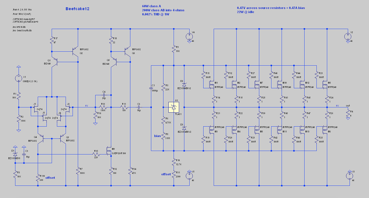
I drew that. But not worries, squashed toes is how I learn.I don't know who drew this or if I am stepping on toes, but I got my boots on....
What I have drawn is just a cascode, isn't it? I did try a current mirror (thinking it would perform the voltage protection of the cascode as well), but it didn't. It appears I would need both if I went with a current mirror."LPT trim" seems unnecessary. A current-mirror will force input current balance. That may cause a voltage offset (MOSFETs are so inconsistent) but this can be trimmed while maintaining the more-important current balance. Also the R110 approach assures asymmetric limiting to M9 while a mirror has hope of symmetry (as D.Self(?) shows, not always that simple).
He he... it did to me too. Which was the impetus for this thread. 😉Since input is small-signal and the "VAS" is "medium signal" it seems odd to find 33mA in the input and 5mA in the VAS.
I currently have the LPT at 12mA and the VAS at 28mA, but I'm still playing around trying to figure out if the LPT current affects the H2/H3 ratio.
The driver will be either a SemiSouth JFET or an IRF610 (both are TO-247s). So I can radically increase the VAS current if needed. Based on your, @ZM's and @Mark's feedback, it sounds like at least some increase is in order.
The original idea was to have the input stage, VAS and OS bias circuits in one box and those ugly MOSFETs in another. So a lack of global feedback simplified things (and might have been an issue over a long wire?). But now I'm thinking driving the MOSFETs over a long wire might also be an issue, so maybe everything belongs in the same case after all. (In which case I'd have a jumper for feedback as I have no idea yet what my taste is.)Not even going to comment on having a potentially good gain-amp and then omitting all extra NFB around a bunch of ugly output MOSFETs, because I suppose that is a matter of taste.
Cheers,
Jeff.
PS: the "example" was a bit old; here's my current thinking:
Attachments
The LTP current didn't appear to have any affect on the H2/H3 ratio. So I put the LTP at 18mA.
I ran Mark's suggestion and got 60mA for the VAS, give or take. (The limiting factor in this circuit is the CCS BJT rather than the driver JFET.)
Sound reasonable?
I ran Mark's suggestion and got 60mA for the VAS, give or take. (The limiting factor in this circuit is the CCS BJT rather than the driver JFET.)
Sound reasonable?
didn't tried SJEP with so sissy current , but something is telling me that you're wasting it there
- Status
- Not open for further replies.
- Home
- Amplifiers
- Pass Labs
- How to choose VAS current