Greetings, I have just finished building my F-5. The Build Guide from 6L6 was very helpful. I have it biased correctly and it sounds very nice.
I have a couple questions. Perhaps I should be asking these questions in an existing thread. If so, will someone please point me in that direction.
I am getting a slight hum even with the volume all the way down or with the preamp disconnected. I tried to follow best practices for internal wiring: cross psu wires and input/output at 90 degrees; keep input and output wires separated, etc. I think I followed the revised grounding scheme from the thread. But obviously I've missed something. It would be great to have a couple suggestions of what to look for.
The PSU is based on the DIT store universal PSU, built according to the schematic for the PASS F5 PSU.
Also I wondered if there are any particular guidelines for a preamp? I am building a B1 but in the interim I am using a McIntosh C36. I wonder if this is contributing to the problem?
Attached are a couple photos. I appreciate any assistance you can provide. Thank you.
Attachments
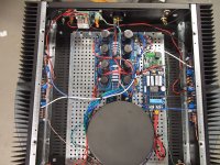
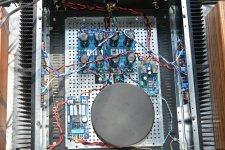
What's that lone CL-60 doing up near the front of the chassis? I can't see what it's attached to.
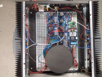
Your quest for symmetry is hurting you. Rotate the PSU board counter-clockwise 90deg and try to get the diode to PCB wires a lot shorter.
Twist the AC wires from the IEC inlet and get them against the chassis and run them by themselves to the softstart. Having the AC wires mingled with everything else is not going to be quiet.
You might want to reconsider the side you've got the softstart mounted on, the AC's journey from there to the power switch and back is pretty darn long.
Same with the white DC wires from the bridge to the power input of the speaker protection board - that's a long untwisted pair and going to be noisy as it's got all the ripple on it.
What's the green board, a temp monitor? Is it powered by the little blue buck converter? Disconnect that to see if it's polluting the PSU. The good news is the possibility of a single-pair F5 heat saturating a 5U 400mm case is pretty much not possible unless you ran enough bias to exceed the dissipation rating (in W) of the Mosfets.
For safety the green earth lead from the IEC should ideally only be a few inches long. Run it down to the perforated chassis under the inlet. Make the violet transformer wire long instead.
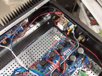
Please post a photo of the output edge of the PSU board.
Your quest for symmetry is hurting you. Rotate the PSU board counter-clockwise 90deg and try to get the diode to PCB wires a lot shorter.
Twist the AC wires from the IEC inlet and get them against the chassis and run them by themselves to the softstart. Having the AC wires mingled with everything else is not going to be quiet.
You might want to reconsider the side you've got the softstart mounted on, the AC's journey from there to the power switch and back is pretty darn long.
Same with the white DC wires from the bridge to the power input of the speaker protection board - that's a long untwisted pair and going to be noisy as it's got all the ripple on it.
What's the green board, a temp monitor? Is it powered by the little blue buck converter? Disconnect that to see if it's polluting the PSU. The good news is the possibility of a single-pair F5 heat saturating a 5U 400mm case is pretty much not possible unless you ran enough bias to exceed the dissipation rating (in W) of the Mosfets.
For safety the green earth lead from the IEC should ideally only be a few inches long. Run it down to the perforated chassis under the inlet. Make the violet transformer wire long instead.
Please post a photo of the output edge of the PSU board.
Last edited:
Greetings and thanks for the great suggestions.
The CL-60 is connected to the ground from the PSU and to the ground post attached to the chassis and ground wire from the mains inlet.
I really appreciate the details you mention and will implement them immediately. I think I understand the reason for each recommendation.
Yes, the little green board is a temp monitor. I'm not running any more bias the it is recommended for in the build guide so I think I just remove the temp monitor. I'm using a 400mm 3U case but, by my calculations, it has the same heatsink dissipation as the 4U 300mm case. It just barely gets warm.
Last edited:
Thanks - That helps.
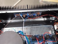
Mount the ground-lift CL-60 as shown. Also attach IEC safety earth to same point the tail of the CL-60 attaches to chassis.
You can bring the shield of the transformer to that spot as well, or just attach that shield (violet transformer wire) to the chassis near the transformer itself.
Mount the ground-lift CL-60 as shown. Also attach IEC safety earth to same point the tail of the CL-60 attaches to chassis.
You can bring the shield of the transformer to that spot as well, or just attach that shield (violet transformer wire) to the chassis near the transformer itself.
Excellent. I started on these changes yesterday. I decided to swap the cheapo speaker protection circuit for the DIY version. At first I couldn't make it work and then I discovered I had transposed the zener from "4735" to "4753" which switc hed the zener voltage from 6.2 to 36 - and of course it wouldn't come out of protection. So when I get the new diode later this week (I hope) I'll finish the setup.
I did shorten the connection from transformer to bridge and rotated the PSU as you suggest, so those leads will be much shorter. I will also move the speaker protection much closer to the transformer so those leads are much shorter. And will twist all the wires as much as possible. Also removed the heat sensor and buck converter. I've got my fingers crossed.
As you saw, I used rectifier bridges. Would it be even better to use the diode board that comes with the DIY Audio universal PSU? This would reduce the connection even further. And maybe those soft recovery diodes would be even quieter. What do you think?
Thanks again for all the information. I have a PASA ACA amp that I really like (built my own PSU instead of the laptop supply). So I'm looking forward to getting the F5 up and running. And then I think I'll tackle an Aleph J...
One or the other should be fine. I also recall another hum troubleshooting thread where the culprit turned out to be the transformer itself, moving it further away from the rest of the circuit got rid of the hum. I’m on a similar path as you, some low level hum in my f6. I’ve gotten hold of schottkys and will try to replace bridges with diyas diode boards, but will also try to move the transformer further away to see. Haven’t had time yet, but will keep my eyes on this thread and report back if there are any relevant news ")
One or the other should be fine. I also recall another hum troubleshooting thread where the culprit turned out to be the transformer itself, moving it further away from the rest of the circuit got rid of the hum. I’m on a similar path as you, some low level hum in my f6. I’ve gotten hold of schottkys and will try to replace bridges with diyas diode boards, but will also try to move the transformer further away to see. Haven’t had time yet, but will keep my eyes on this thread and report back if there are any relevant news
Thank you. I will let you know when I get the new zener and put it all back together. I'm not sure where I'd move the transformer to get it farther from anything. Replacing the rectifier bridges with the diode board is my next step, I suppose.
No, I’m also scratching me head about that, it’s pretty tight with space already. I have bought an L-bracket and will mount it vertical on that to see. I might start by simply removing it from the chassis as a test, but the practical implementation is not obvious if that turns out to be the trick... You have a nice shielded Trafo so in your case it might be less of an issue.
Yes, toroid transformers have an EMI pattern that is very dependent upon position so it is very possible that orienting it differently could make a big difference. I had a phono preamp that would not be quiet with the transformer in the same case. 6 inches of separation cleared it up nicely. No reason that I can see that you couldn't put the transformer and diodes in a separate case - or even the entire power supply.
Success. I made the recommended changes and now the hum is virtually gone. I can detect a slight hum about 2 inched from the speaker cone but I'd say that's acceptable.
Here's what I did:
Moved the softstart board to be as close as possible to the power switch. Rotated the transformer to shorten the leads to the softstart board.
Shortened the leads to the bridges.
Rotated the PSU board to be closer to the bridges, thereby shortening the wires from the bridge to PSU board.
Used the DIYAudio speaker protection board instead of the original cheapo one. I ended up powering it from the PSU since I wasn't sure ho to get a ground reference if powering from the bridge. Moved for shorter wiring of power to this board.
Twisted all wires. Crossed power wires at 90 degrees to signal wires. Kept speaker leads from being parallel with input.
Removed the DC buck converter and heat sensor.
Thanks for all the assistance.
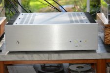
That is useful information - i agree it looks very nice in that case. The extra length is also useful for separating power transformer from the rest of the build in cases like F6 or M2. I wonder, what is the heatsink requirements of F5 compared to those two? I am building up to an M2 build, and wonder if 3Ux400mm would be enough for that amp also? Though i suppose it requires the holes to be hand-tapped...
I think the heatsink requirement is included in some of the articles about the amp (at least it was included in the original article on the F-5 by Mr. Pass. The thermal conductivity of the cases is available on the DIY store website.
Yes, this case did not have pretapped holes. Drilling and tapping is not particularly difficult if you have a drill press (don't use it for tapping, however). Heatsinks are soft aluminum. Be sure to use cutting oil.
Yes, this case did not have pretapped holes. Drilling and tapping is not particularly difficult if you have a drill press (don't use it for tapping, however). Heatsinks are soft aluminum. Be sure to use cutting oil.
...Drilling and tapping is not particularly difficult if you have a drill press (don't use it for tapping, however). ....
DO use the drill-press for tapping... only UN-PLUG it first!! Turn the chuck with the end of the chuck-key. The press will keep the tap very square and centered.
- Status
- This old topic is closed. If you want to reopen this topic, contact a moderator using the "Report Post" button.
- Home
- Amplifiers
- Pass Labs
- Slight hum from F-5