I took a different tack in fusing the amp. I did a mains fuse, and then rail fuses for L/R and +/- for each channel so there are five fuses in total. The amp is complete and went well other than same rework I had to to replace pots on voltage gain stage. I was able to successfully bias the VGS. I then moved onto biasing the output boards and all went fine. I biased for 0.3V across the 1 ohm resistors and got DC offset to zero. It looked well until I hooked it up for testing. I turned volume up slowly and noticed no output from one channel. The other channel was perfect. I check the fuses for the channel that didnt work and to my surprise both + and - fuses were blown for the channel. So I disconnected inputs and outputs and replaced fuses. I was able to see BIAS was working but +ve fuse blew after a few seconds and then about 5 seconds later the -ve fuse blew. I am worried a bit about the VGS but it shouldn't matter as it doesnt pass anything onto the output as it is cap coupled. Any ideas on what the problem could be with the bias board or output stage?
Last edited:
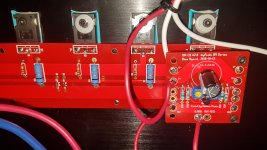
Here is what happened. Everything is correct polarity wise. I checked voltages and made sure everything was OK. I was able to successfully bias the channel in question and also get the DC offset to zero. I did the same for the other channel. It was when I went to do a sound test that the problem occurred. I turned the volume up very slowly and did not get any sound at all from the channel in question. When I checked the 3 A fuses had blown. Even at 3A they should not have blown as it was very low volume and I never heard any sound at all from that side, the other channel works perfectly. But I decided to try again with larger fuses and now I cannot even bias the channel 5 A fuses pop right away. The problem is on the ouput board as I can disconnect the rails from it and then the fuses do not pop. V- is -32 V and V+ is +32V. I have also attach a picture. I also checked to make sure Pchannel and Nchannel are in the correct spots.
Attachments
The fuses are in the supply lines that go to the channel. There is one fuse in the +32V line and another fuse in the -32V. The fuses are mounted on the rear panel. It is both fuses that are failing. I am starting to think that an output transistor(s) died but thought I would ask and see if anyone else encountered this.
Last edited:
Are you sure that I can measure impedance to ground as their is no ground connection in the circuit and there are resistors attached to the gates and sources? See attached PCB. What I did check is the impedance between all the pins on each transistor and there are no shorts.
Attachments
Last edited:
Yes, attach one lead to the heatsinks and check each pin for resistance. It should not be any. I use the buzzer function of the multimeter when checking for continuity. More than likely one of the mosfets is shorted to ground. Think about it, the insulator pads are there to keep the mosfets from shorting to ground. That is the reason they are there.

")
Not going to run them as I know they will get hot real fast. I just want to see if the unpowered impedances are the same. I am leaning towards a bad output transistor as the drain and source should not be close to a short circuit. I am thinking that maybe on popped when I powered up and that was the end of that channel. I left you a couple of questions over on my thread about the F5 turbo
Those mosfets are pretty tough. Be sure there is not something under the insulator pad that pierced it when tightening down. If you tapped the holes yourself you have raised the metal at the hole which needs to be filed or sanded down. If that is not the problem more than likely the bias was too high on fire up.
Pass DIY Addict
Joined 2000
Paid Member
If you tapped those threaded holes into the sink yourself, there is the possibility that you have a metal sliver grounding the back of the mosfet to the sink.
As a side note, not related to your problem, those mosfet insulating pads look rather thick to me - what are they? Some of the sil-pads have a backer that needs to be peeled before using.
As a side note, not related to your problem, those mosfet insulating pads look rather thick to me - what are they? Some of the sil-pads have a backer that needs to be peeled before using.
The insulator is actually a special ceramic insulator/heatsink made specifically for this type of job. The blue is just there so you know which side is which as one side is sticky and the other isnt. I've had to work so I have not had much time but hopefully can figure out what is going on with that channel.
I checked everything and no shorts to the ground and there were no blown parts. This baffled me as the fuses continued to blow. So I switched output boards -left became right and right became left. The bias boards are hardwired to the output boards so they had to be swapped as well. Much to my surprise the other channel also blew fuses when mounted in the same location. Could it be the front end? Well that is pretty doubtful as it is cap coupled and cant pass DC. to make sure I just disconnect the front end board and still kept blowing fuses. In the meanwhile I had been building another project that required me to make heat sink holes as well. I noticed that the holes drilled later were shallower than than the holes drilled earlier. What was happening was that the height setting was drifting slowly on the drill press. To make a long story shorter the root cause was that I could not tighten down the heatsinks enough. It was oh so close but not enough. It appeared to be tight because the screw was bottomed out but the heat sink was not completely tight. I learned two things. On is I have to say I was amazed how fast the bias current took off. The other one is that having each channel's power supply lines fused will save one from destroying parts. I used 5 fuses in total. One on the mains and then two each for the L+R supplies.
- Status
- This old topic is closed. If you want to reopen this topic, contact a moderator using the "Report Post" button.
- Home
- Amplifiers
- Pass Labs
- BA-3 blowing fuses