logic is quite simple , me personally being used to make much more complicated and less possible ookups :
1.instead on Edcor PC600/15K , eyes fell down on Jensen 123flpch laying on bench
2.instead of taking square of 4 , there was just 4 accounted in calculus (wadamistaka) , which is completely easy to do , considering constant squek of Greedy Boyz , shoutng "More! More! More! More!)
3. so , there it is ...... xformer (plus OS) having roughly 24K (indeed close , taking in account losses ) divided with 4 (voltage transfer ratio of Jensen repeater used as autoformer) , instead of 4^2 ...... is giving 6K
which is soso easy load for anything , except sissy toob preamps (if you make it as from Yore , and majority are)

or is it more likely that NP is simply Bad Boy , expecting lavish jump in sales , as result of his malevolence

1.instead on Edcor PC600/15K , eyes fell down on Jensen 123flpch laying on bench
2.instead of taking square of 4 , there was just 4 accounted in calculus (wadamistaka) , which is completely easy to do , considering constant squek of Greedy Boyz , shoutng "More! More! More! More!)
3. so , there it is ...... xformer (plus OS) having roughly 24K (indeed close , taking in account losses ) divided with 4 (voltage transfer ratio of Jensen repeater used as autoformer) , instead of 4^2 ...... is giving 6K
which is soso easy load for anything , except sissy toob preamps (if you make it as from Yore , and majority are)
or is it more likely that NP is simply Bad Boy , expecting lavish jump in sales , as result of his malevolence
It so happens that prototypes of the next DIY amplifier are on my bench
anyway, so I measured several examples.
Nothing but the facts, ma'am.")
The primary load with the Edcor used 1:5 and with 23.5K secondary load
is 795 ohms.
Distortion of the transformer with 25 ohm source and 1 KHz is .02%
from about 1 watt to 25 watts (equivalent voltage, 8 ohms).
The distortion from the Toshiba Jfet buffer is less that that up to the
25 watt equivalent output.
For the Jensen JT-123-FLPCH set up as a 1:4 auto-former, and under the
same test conditions, the primary load was 1.20 Kohm. Distortion
was about .003%.
For the Cinemag CMOQ-4LPC, also a 1:4 auto-former, the load was
1.25K, and the distortion was .002%
anyway, so I measured several examples.
Nothing but the facts, ma'am.
The primary load with the Edcor used 1:5 and with 23.5K secondary load
is 795 ohms.
Distortion of the transformer with 25 ohm source and 1 KHz is .02%
from about 1 watt to 25 watts (equivalent voltage, 8 ohms).
The distortion from the Toshiba Jfet buffer is less that that up to the
25 watt equivalent output.
For the Jensen JT-123-FLPCH set up as a 1:4 auto-former, and under the
same test conditions, the primary load was 1.20 Kohm. Distortion
was about .003%.
For the Cinemag CMOQ-4LPC, also a 1:4 auto-former, the load was
1.25K, and the distortion was .002%
Thanks for the measured data! The Edcor's Zin is higher than the prediction from [23.5K / (1 + turnsratio)^2] and the other two transformer's Zin are lower than math predicts.
Folks who contemplate replacing the Toshiba JFET buffer with "something else": you now know where your minimum-acceptable-performance target lies.Distortion of the transformer with 25 ohm source and 1 KHz is .02%
from about 1 watt to 25 watts (equivalent voltage, 8 ohms). The distortion from the Toshiba Jfet buffer is less that that up to the 25 watt equivalent output.
This reminds me of that time I defended Pons and Fleischmann.
But Michael, that was nearly thirty years ago !
At that time I was still a scientist myself ...
To keep with the off-topic topic a bit longer, what do you think of Helion Energy ?
Best regards,
Claas
It so happens that prototypes of the next DIY amplifier are on my bench
anyway, so I measured several examples.
this sounds like it might be that secret relabeled ACA with an M2ish input?

I will be making that one to try to soften the mids in my tri-amped OB (F5+ACA+ACA), though I must say the original ACA is already sooo good in that limited role that it might be a stretch to beat that performance. But packaging 2 channels in one housing is an added incentive; the second one is that I never experienced these Edcors, Jensens etc.; (after that I only have "to worry about" putting to use the 4 pairs I have of 201/1530 Toshibas. I am probably close to that point which ZenMod cited as having it "good enough" and just messing around for the sake of DIY (as these days I find myself more often opting for listening to music than going to my workbench
).I measured two samples of the Edcor PC600-15K transformer used in the First Watt M2.
The end-to-end DC resistance of the primary (pin1 to pin3) averaged 44 ohms.
The end-to-end DC resistance of the secondary (pin7 to pin5) averaged 235 ohms.
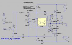
See whether you are able to use these measured values, along with the transformer's frequency response curve (attached below), to calculate a lower bound for the inductance of the primary and the inductance of the secondary. Remember that this transformer is marketed as a "600 ohm to 15 Kohm line level matching transformer". I predict it won't match the inductances I measured on these transformers, not even close. Buy a few and measure them yourself, they cost less than $8.
_
The end-to-end DC resistance of the primary (pin1 to pin3) averaged 44 ohms.
The end-to-end DC resistance of the secondary (pin7 to pin5) averaged 235 ohms.
See whether you are able to use these measured values, along with the transformer's frequency response curve (attached below), to calculate a lower bound for the inductance of the primary and the inductance of the secondary. Remember that this transformer is marketed as a "600 ohm to 15 Kohm line level matching transformer". I predict it won't match the inductances I measured on these transformers, not even close. Buy a few and measure them yourself, they cost less than $8.
_
Attachments
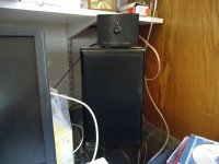
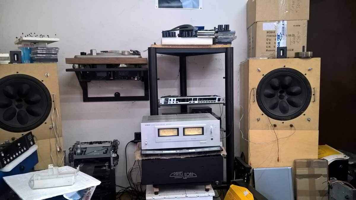
why not combine both - muzak and bench?
My desk, Jordan J92's and ACA's
Attachments
One of my current projects is a no-Toshiba-JFETs reimplementation of the M2, using a replacement front end that can happily drive a 50 ohm load to 5V RMS, all day long. The M2 spec of 650 ohms and 3V RMS, becomes child's play.
JFET input of course, but 2018 active production rather than Toshiba unobtanium. And a couple of other heretical deviations from First Watt dogma, which loyal fans may find disagreeable.
Did you ended up to a new front end? One of the multiple from M2X?
That quote in #38 was posted on 13 March 2018.
Six weeks later, on 26 April 2018, I announced M2x with four input daughter cards. Three of them were indeed no-Toshiba-JFET reimplementations of the M2. In the subsequent months and years, another three input daughter cards (free of Toshiba JFETs) have been announced and delivered. So now, as of today, there are six different ways to build an M2 without Toshiba JFETs. And there is also "Ishikawa" in case you want to try the original, WITH Toshiba JFETs.
https://www.diyaudio.com/forums/pass-labs/321925-diyaudio-watt-m2x.html#post5416399
_
Last edited:

- Status
- This old topic is closed. If you want to reopen this topic, contact a moderator using the "Report Post" button.
- Home
- Amplifiers
- Pass Labs
- Perplexed about M2 amplifier circuit impedance: schematic vs. user manual