Hello Nag. I have one more post to publish on using DEF in a common gate configuration. I hope that it will be informative and answer your very good questions above. Have you assembled a DEF?
Thank You.
No I didn't assembled DEF amp still,I am still looking working circuit .
recently I built lm1875 stereo amp using official circuit and diyaudio community help and it is excellent. After reading lot of posts i am fascinated about passlabs amps. I have same concerns as Mr. Papa too many components complicate the circuit and honestly I don't know which component will do what and harmonic distortions bla bla. So I checked the forums and excited about F7 amp which very less components and I decided to implement F7. later I found DEF thread which has less components compared to F7. So i decided I want to Build DEF. Even I am concern about audio transformer which is form of inductor and it will opposes sudden raise in signal (some high school knowledge) and it will alter my sound quality.
here is my plan.
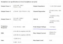
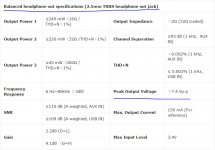
good headphone amp which will take input from my laptop usb and has some Max 7 Vp-p output which can be feed into DEF final stage of power (two depletion enhanced mosfets).
Thank You.
No I didn't assembled DEF amp still,I am still looking working circuit .
recently I built lm1875 stereo amp using official circuit and diyaudio community help and it is excellent. After reading lot of posts i am fascinated about passlabs amps. I have same concerns as Mr. Papa too many components complicate the circuit and honestly I don't know which component will do what and harmonic distortions bla bla. So I checked the forums and excited about F7 amp which very less components and I decided to implement F7. later I found DEF thread which has less components compared to F7. So i decided I want to Build DEF. Even I am concern about audio transformer which is form of inductor and it will opposes sudden raise in signal (some high school knowledge) and it will alter my sound quality.
here is my plan.
good headphone amp which will take input from my laptop usb and has some Max 7 Vp-p output which can be feed into DEF final stage of power (two depletion enhanced mosfets).
Hello Nag. The bold statement in your post will work fine. Ensure that no DC offset is present at the output of the laptop, headphone amp and DEF. If a DC offset [voltage] is present, use coupling capacitors between devices so as to protect them. I hope that you can view the BAF2017 YouTube by Mr. Pass. It is enjoyable and highly informative. He explained very well the DEF design etc. A kit will be available at the diyaudio store to assemble.
Negative Current Feedbackl [NCF]
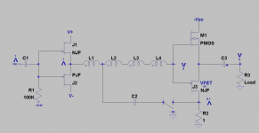
I proposed in post#216 the use of Positive Current Feedbackl [PCF] in a simplified schematic of DEF or DEFiSIT by Mr. Pass. Negative Current Feedback [NCF] is also possible as shown in the attached schematic. Please note the following:
1. The schematic is like that shown by Mr. Pass at BAF2017. It is applicable to DEF and DEFiSIT.
2. I flipped the output stage so that ground is at the bottom.
3. The drain of N-SIT or N-JFET is grounded via a 1 Ohm example sense resistor.
4. Current flowing through the sense resistor also flows through the loudspeaker [Load]. The resultant voltage drop across Rsense is the NCF voltage generator..
5. The V letter symbolizes the absolute phase of the music signal and a number [1, 4..] on it reflects its amplitude.
6. The power amp as written inverts phase.
7. The sense voltage is in phase with the input signal because it is collected at the drain of SIT or N-JFET.
8. Without NCF, Capacitor C2 grounds the primaryy winding of the autoformer. The amplitude of the music signal across this primary winding is 1Vac which is amplified by the autoformer and presented as 4V to the gates of the FETs.
9. With NCF engaged via capacitor C2, the new voltage drop across the primary winding is [Vin -Vncf] = the example of 0.9V.
10. Less current now flows through the primary winding with NCF versus without it. And so the output voltage of the autoformer will decrease in proportion for presentation to the Load.
What is the sonic value of NCF? It is overall negative feedback; but is solely sensitive to the value of load impedance which is a function of frequency and thus affects current flow through it; like PCF is. It acts as a current limiter of the output stage due to a low transient loudspeakler impedance, and possibly protect the FETs from overdrive.
Attachments
Thanks Mr. Pass for this info. Please point to an example circuit if its no hassle.NCF is routinely used to make current source amplifiers with high output
impedance.
Experimenting with DEF wired in Common Gate configuration
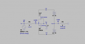
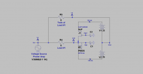
This post talks about the practical value of using DEF in a common gate configuration [CGC]. I have simplified the attached schematic. DEF is idealized for simplicity; like that shown by Mr. Pass at BAF2017. Ditto for the voltage-source power amp which is shown on the left of the schematic as a power signal source delivering lots of output current into the 8 Okm load and the DEF. This power amp can be a diyF5 or your choice. Here's a list of relevant details:
1. The 8 Ohm loads can also be twin loudspeakers. They are oriented in the sound space for stereo reproduction. Each is an A/D/S L-730 which is a 3 ways boxed speaker of great performace.
2. The inverted V letter shows the absolute phase, and the number above it is the amplitude of a 100 Hz ac test signal. CGC DEF does not invert the phase of the processed ac signal from basic electronics, and was verified by measurement.
3. It also follows from basic electronics that the magnitude of the current injected at its joined sources exits at/with an equal amplitude from the joined Fet drains.
4. The impedance of DEF looking at/in the joined sources of its Fets is calculated to equal ~300 millOhms, from the input 8 Ohm load resistor and the ac amplitude data.
5. Basic electronics says the common gate amp has a high output impedance at the zero Volt junction of the PSU batteries. Thus it is a current source amp.
Here's the bottom line and the value of this arrangement:
1. The great sonic performance of the LEFT loudspeaker [in schematic] which is driven by the voltage source power amp can be fully attributed and/or equated to the ac current flowing through it. This driving current embodies/bears all of the parameters which enabled the LEFT loudspeaker to excel.
2. This same current above bearing all of the sonic performace attributes [and ills] of the LEFT loudspeaker, exits the DEF CGC current source amp [atheir joined drains] and enters/enegizes the RIGHT loudspeaker. The sonic performance of the RIGHT loudspeaker can only be almost identical to that of the LEFT loudspeaker; because the same music current is simultaneously energizing both loudspeakers with the same phase, amplitude and sonic attributes.
3. The RIGHT loudspeaker is enegized by DEF CGC current source amp [CSA]. It suggestes that there will no need to re-wire its X-over plumbing; because this CSA is now behaving electrically as a performnce twin of the voltage source amp.
4. Got twice the sound pressure [theoretically]. Either loudspeaker can be at one location and the other at a remote location which is acoustically distant from the first.
5. The performance of this arrangement is lovely and superb by using my Threshold S/150 or KENWOOD KR-6050 voltage source PAs, with my prototype DEF which is the same one I've shown in past posts.
Attachments
Thanks Mr. Pass for this info. Please point to an example circuit if its no hassle.
Rod Elliot wrote about this and provides some examples:
Variable Amplifier Impedance
Thank you Mr. Pass for the reference. The current amp in Fig 1. clearly shows the application of Negative Current Feedback therein. It fits the description of its application to DEF/DEFiSIT. I will further study this article to grasp its sonic value.
Best
Anton
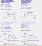
Interesting technical note. I see that with "Improved Howland Current Pump" in figure 6 is essentially the same circuit as my "Type-1" Positive Current Feedback circuit in DIYAudio thread "FirstWatt F7 Review", except that the input and ground to the opamp are reversed. Thus flipping the inputs changes the amplifier from near-zero output impedance to near infinite output impedance.
I cannot find the posting number because for some reason the entire thread is unavailable at DIYAduio. Here is the circuit shown there"
Attachments
Last edited:
") )
)
Why do threads go dead after I make a posting?
The same thing happened with F4 Beast Builders.
People like looking at porn more than journal articles.
Hahaha


Still experimenting with DEF wired in a common gate configuration
Wishing you all a safe, healthy and prosperous 2018.
The attached schematic is another application of DEF. Please note the salient changes it has compared with an earlier one:
1. DEF is biased [idle current] at 120 mA or Class AB instead of ~1.3A. Will it still sound great? Yes is the short answer; because the "performance" of this DEF defaults and/or is cleaned up by the voltage source amp [Threshold S150].
2. When DEF bias is decreased [-Vgs] of the depletion FET [SJDP120R085] becomes more negative in value, and the [-Vgs] of the enhancement P-MOS [IRFP9140] becomes less negative in value; with both of the new [-Vgs] values relative to their high bias states. Suppose one has an "ideal" DEF or DEFiSIT whereby ideal means that both FETs initially share a unique [-Vgs] at a constant PSU value, and a high bias. If [by example] the voltage control which is common to [-Vgs] is made more negative, the [- Vgs] of SIT or R085 moves towards cut off, and that of P-MOS moves towards more conduction. No damage to the devices happens; but the original output voltage quiescent point will drop towards the negative rail and thus alter the initially ~equal Vds values at high bias.
3. The input impedance doubled to ~0.7 Ohms [relative to ~0.3 Ohm in previous exp.] at the joined sources of DEF. This joint common source has an explicit value for use as Positive Current Feedback [PCF]. It generates a voltage signal which is proportional to the current flowing in the bottom loudspeaker. This PCF signal may then be used to alter the performance of the voltage source amp as already known. A still higher-valued PCF signal is available at the output of DEF driving the upper loudspeaker.
4. In a separate experiment DEF was operated at a 10 mA bias. It still sounded good and judged fully agreeable. But the sound of this bias-starved Class AB system changed for the "subjectively better" at the higher bias levels.
5. Not shown in the schematic is a zener [8.4 V] which is connected between the gate of R085 and the joined FET sources. It protects both FETs with a priority for R085.
Attachments
- Home
- Amplifiers
- Pass Labs
- DEF Amp