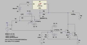
The attached schematic, and its LTSpice simulation are for a Class A power amp which spun-off the last 4 posts of the thread Class aP amplification in this Forum. These posts detail the genesis, and works of this amp.
The results of the simulation are quite interesting; granted they are not a fluke. They show that the NPN Darlington is the predominant contributor to the current flowing through the 8 Ohm load. The magnitude of the currents are readily sensed flowing through the load resistor [8 Ohm], the emitter resistor of the Darlington [1 Ohm], and the 1 Ohm resistor in series with the IN port of LT317A.
The results of the simulation are quite interesting; granted they are not a fluke. They show that the NPN Darlington is the predominant contributor to the current flowing through the 8 Ohm load. The magnitude of the currents are readily sensed flowing through the load resistor [8 Ohm], the emitter resistor of the Darlington [1 Ohm], and the 1 Ohm resistor in series with the IN port of LT317A.
Attachments
More info
There is more to describe the operation of this Class A amp which embodies a dynamic load comprised of LT317A [a variable +ve voltage regulator], and its associated control circuits. One may wish to toy with its asc file by changing only the values of the power output load resistor [e.g. 4, 8, 16 Ohms] and determine the relative current contribution of LT317A and Darlington to the load. At 4 Ohms load, LT317A contributes to the current flowing through it; unlike at 8 Ohms load. Also note the current and its quality flowing through the 280 Ohm resistor which connects the OUT to the Adjust ports of LT317A.
The simulated THD is ~0.04% at each load. I have prototyped 4 assembled units of the sub-Class A amp; with each Darlington [TIP120] idling at 100 mA. Their collectors will be tied together. I also have 2 assembled units of the dynamic load. I'll integrate the system and hear it.
Attachments
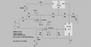
The attached schematic is another example of this Class A power amp which now advocates using two LT317As. The upper LT317A is configured as a normal voltage regulator whereby its Vout = 1.25 V[1+2.2K/0.248K] = 12.4 V. The lower LT317A is configured as a special power NPN operating in a common emitter configuration. Here are salient properties and further thoughts:
1. Both LT317As idle at 0.5A as they are connected in series.
2. LT338 or its equivalent LM338 have a higher power capability than LT317A, and either can replace it in this proposed application
3. Should one object to using the power NPNs in LT317A, there is an LM783 which uses N-Channel power Mosfets instead [of NPNs].
4. The voltage gain of this amp equals 8; which is that of the upper LT1001A OpAmp configured as a phase inverter.
Let's talk about the contribution of output current to the load by the upper and lower LT317As:
1.The maximum current from the lower LT317A is constant at [0.9 Ap-p] regardless of the value of the loads 4, 8, 16 Ohms.
2. The output voltage 7.2 Vp-p [Vin *2*8] across the shown 4 Ohms pushes a maximum 1.8 Ap-p through it.
3. It follows that the upper LT317A contributes 0.9A p-p to the load; such that the sum current contribution of both LT317As equals 1.8 Ap-p, and thus satisfies Ohm's Law.
4. For an 8 Ohm load, the current flowing it is mostly contributed by the lower LT317A.
5. For a 16 Ohm load, the current flowing through it [0.45 Ap-p ] is all from the lower LT317A; but the excess current [0.45 Ap-p] is soaked up by the upper LT317A.
6. The above observations are the simulation results.
Be patient when running the asc file; so as to get a meaningful simulation.
Attachments
The 10mF cap between the amp outand the 8r0 load blocks DC. As a result only AC can flow to the 8r0 load.
So, how do you arrive at:
So, how do you arrive at:
Are you talking about AC current or DC current?They show that the NPN Darlington is the predominant contributor to the current flowing through the 8 Ohm load.
The 10mF cap between the amp outand the 8r0 load blocks DC. As a result only AC can flow to the 8r0 load.
So, how do you arrive at:
Are you talking about AC current or DC current?
Hello AndrewT.
The short answer is AC.
1. At idle, LT317A generates a constant voltage [Vout] to the collectors of the Darlington and also supplies a certain DC flowing through it [Ic].
2. An input AC signal [Vin] modulates [Ic], and simultaneously modulates Vout of LT317A.
3. This modulation transforms the Darlington to a voltage-variable current source, or an AC generator.
4. This modulation transforms LT317A to a voltage-variable voltage source. This voltage-variable output [AC] voltage = Vin*2*8.2. The value of 8.2 is the gain of the OpAmp inverter modulating LT317A.
5. The resultant AC condition at the collectors of the Darlington proceed to satisfy Ohm's Law for/in the load 8r0.
NB. In my previous post, the correct name of LM783 should be TL783.
- Status
- This old topic is closed. If you want to reopen this topic, contact a moderator using the "Report Post" button.