Pics again
Thank you Rich, already had one on order and schedule for a Monday delivery. The electrical tape was/is very temporary to hold the toroidal in place as I was arranging the amp and connections.
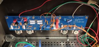
I also just noticed I have the speaker outs running behind the input in my last picture. Not ideal but as I mentioned in my previous post, I have dead silent background so I am not going to bother at this point.
Lets try these pics.
Thank you Rich, already had one on order and schedule for a Monday delivery. The electrical tape was/is very temporary to hold the toroidal in place as I was arranging the amp and connections.
I also just noticed I have the speaker outs running behind the input in my last picture. Not ideal but as I mentioned in my previous post, I have dead silent background so I am not going to bother at this point.
Lets try these pics.
Attachments
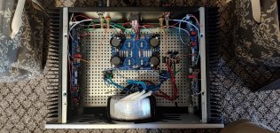
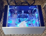
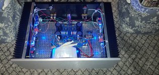
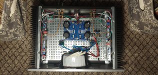
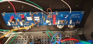
When you get the metal bracket for mounting your transformer, make note of the orientation as it is currently, and try to remount it in the same orientation. It is likely that you found a configuration that was less conducive to producing hum.
Oh, and the unpopulated cap locations in the PSU are driving me nutz. That’s my problem, not yours, but you do have an opportunity to try something. After you have had a few days to listen to your new amp , try installing some high quality* capacitors of 2200 uF or 4700 uF in those empty spots. Listen to the amp some more.
* I like Nichicon KG or KS series
Tungsten, can I get away using snap in capacitors without soldering then? Otherwise I'd be real hesitant to pull the power board out to solder additional caps. I appreciate the idea.
Think of removing the board in order to solder the caps as an opportunity to improve the method of mounting it to the perforated baseplate . It should be mounted on standoffs using the holes in the board intended for that purpose .
Ok, now I see the mounting points.
I still recommend soldering the snap-in caps. That’s the only way to guarantee a proper gas-tight connection.
I still recommend soldering the snap-in caps. That’s the only way to guarantee a proper gas-tight connection.
Oh, and the unpopulated cap locations in the PSU are driving me nutz.
* I like Nichicon KG or KS series
What is this about?
^ This is about providing a low impedance power supply over a broader frequency range. The larger capacitors, such as used in this most recent example, do an Ok job at energy storage and at setting the dominant low frequency pole for the amplifier, but they do become more inductive at higher frequencies. I think this is more an issue with large bulk caps in the 33mF range and up, where builders tend to use a small number to get the total capacitance figure. I have found noticeable improvements when adding smaller value caps, preferably a decade or more apart in capacitance to improve the overall filtering of the power supply. Reducing the capacitance by a factor of ten increases the self-resonant frequency by a factor of about three, or more due to reduced inductance of the physically smaller parts. Since smaller capacitors are less expensive, it is easy to use high quality parts designed for audio use.
This is a well understood phenomenon in the computer electronics industry. Capacitor manufactures have published white papers on the subject. Admittedly the frequency ranges are quite different (MHz vs kHz), but the concept is the same.
This is a well understood phenomenon in the computer electronics industry. Capacitor manufactures have published white papers on the subject. Admittedly the frequency ranges are quite different (MHz vs kHz), but the concept is the same.
I had just watched this video on Wednesday. His videos are exceptionally informative for a guy like me trying to learn basics. It covers above quite nicely, and to TA's point it also applies to lower frequencies. He has another video on bypass electolytics also. His graphs made it hit home. I'm a very visual learner.
EEVblog #859 - Bypass Capacitor Tutorial - YouTube
EEVblog #859 - Bypass Capacitor Tutorial - YouTube
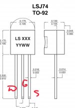
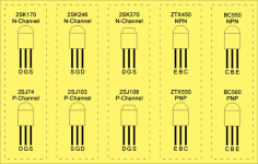
Should the jfets be hot? Around 50 degrees? Are the pins correct (please consider the image attached)? I'm using lsj74f
Attachments
Last edited:
say 5mA , multiply with rail
you're 100mW and up
50C is sane
Thank you, ZM
I edit old picture with transistors pin details.
Old one was blurry and pain to watch.
Feel free to save. 🙂
Thanks, mate 🙂
^ Since smaller capacitors are less expensive, it is easy to use high quality parts designed for audio use.
.
I wasn't asking about that.
I meant who/what were you referring to about unoccupied capacitors?
Not sure which small caps you are referring but the equivalent capacitance converted to Panasonic FC is not cheap.
You could get most of what you needed by putting some pansonic FC caps in parallel with the bigger caps. That's just a suggestion since you brought this topic up. I was just asking about where were these missing caps you were referring to.
This could be helpful to people.
Capacitor Characteristics
This isn't the exact link I was looking for but still useful.
Looks like Rod Elliott has added a lot more content to his site since I last checked there.
Capacitor Characteristics
This isn't the exact link I was looking for but still useful.
Looks like Rod Elliott has added a lot more content to his site since I last checked there.
Last edited:
The recent picture showing the PSU had only half of the capacitor locations populated. I suggested filling the empty locations with smaller value parts. Similar to what you recommend, a combination of large and small value capacitors.I wasn't asking about that.
I meant who/what were you referring to about unoccupied capacitors?
Not sure which small caps you are referring but the equivalent capacitance converted to Panasonic FC is not cheap.
You could get most of what you needed by putting some pansonic FC caps in parallel with the bigger caps. That's just a suggestion since you brought this topic up. I was just asking about where were these missing caps you were referring to.
Rod is a Jewel ........ almost spilled my coffee, when I read - "...words fail me..."

I've been critical of Rod in the past on certain topics, but these updates look good.
- Home
- Amplifiers
- Pass Labs
- Aleph J illustrated build guide