Pearl 2 Build Pics and Help Question!
Originally posted as a new thread (maybe my bad?) with no replies, trying my luck here on the thread that was the inspiration for me to biuld the Pearl 2.
A big thank you to Wayne and Nelson for their selfless giving to the DIY community, great designs and all for the pleasure of making people curious to build and then happy they did!
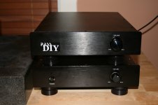
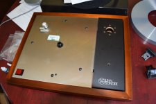
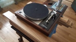
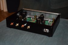
Pics are my Pearl 2 with B1 in same chassis (I don't have a preamp so this gets the job done without one). I can use the B1 with an Aux input (CD, DAC or what have you) or with the Pearl 2 using the switch on the right side panel. The rotary multipole and two pole switch in the middle of the chassis are for cartridge loading options (later).
Frankly it sounds really nice and I am super happy, the Pearl 2 is very natural sounding and the B1 by itself adds a nice touch of Neslon to CD and DAC inputs.
HELP!
The one area I am not sure if I got it as good as it could be is the noise from the Pearl 2. I built it originally with R14 at 362 for high gain and have since changed to 1K for stock gain. There is noise at both gain setups (for sure, more with the higher gain setup but not by that much). In listening with a high output MM cartridge the noise is of no matter but with a LOMC cartrdige I think it will be a big issue.
There is essentially no hum (there was but star grounding took care of that). There is a hiss and a high freq buzz (the buzz is a little louder than the hiss).
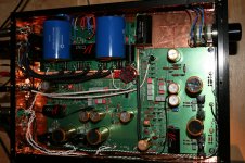
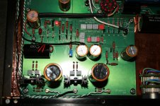
I also have a couple of voltages off from Wayne's drawing. I made notes on the attached:
1) Top of R25 is -22.5 volts (in both high and low gain configurations) vs the -26.2vdc in Wayne's dwg.
2) Bottom of R9 (collector of Q3 is) 12.5vdc vs the 10.1vdc on Wayne's dwg.
These measurements are the same ish in both channels. All other readings are good compared to Wayne's dwg and P1 is set to 0 with about 30mv of swing.
I have tried pulling one leg of R7 and putting a cap on R10 as I have seen mentioned in one of the Pearl 2 threads with no change. I apologize if I have missed any other suggestions already made
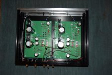
BTW, power supplies are Salas Back In Black shunt regulators, yes probably overkill but that is my way
If anyone has any advice I would be most appreciative!
Thank you all.
Originally posted as a new thread (maybe my bad?) with no replies, trying my luck here on the thread that was the inspiration for me to biuld the Pearl 2.
A big thank you to Wayne and Nelson for their selfless giving to the DIY community, great designs and all for the pleasure of making people curious to build and then happy they did!
Pics are my Pearl 2 with B1 in same chassis (I don't have a preamp so this gets the job done without one). I can use the B1 with an Aux input (CD, DAC or what have you) or with the Pearl 2 using the switch on the right side panel. The rotary multipole and two pole switch in the middle of the chassis are for cartridge loading options (later).
Frankly it sounds really nice and I am super happy, the Pearl 2 is very natural sounding and the B1 by itself adds a nice touch of Neslon to CD and DAC inputs.
HELP!
The one area I am not sure if I got it as good as it could be is the noise from the Pearl 2. I built it originally with R14 at 362 for high gain and have since changed to 1K for stock gain. There is noise at both gain setups (for sure, more with the higher gain setup but not by that much). In listening with a high output MM cartridge the noise is of no matter but with a LOMC cartrdige I think it will be a big issue.
There is essentially no hum (there was but star grounding took care of that). There is a hiss and a high freq buzz (the buzz is a little louder than the hiss).
I also have a couple of voltages off from Wayne's drawing. I made notes on the attached:
1) Top of R25 is -22.5 volts (in both high and low gain configurations) vs the -26.2vdc in Wayne's dwg.
2) Bottom of R9 (collector of Q3 is) 12.5vdc vs the 10.1vdc on Wayne's dwg.
These measurements are the same ish in both channels. All other readings are good compared to Wayne's dwg and P1 is set to 0 with about 30mv of swing.
I have tried pulling one leg of R7 and putting a cap on R10 as I have seen mentioned in one of the Pearl 2 threads with no change. I apologize if I have missed any other suggestions already made
BTW, power supplies are Salas Back In Black shunt regulators, yes probably overkill but that is my way
If anyone has any advice I would be most appreciative!
Thank you all.
Attachments
I have tried pulling one leg of R7 and putting a cap on R10 as I have seen mentioned in one of the Pearl 2 threads with no change. I apologize if I have missed any other suggestions already made
BTW, power supplies are Salas Back In Black shunt regulators, yes probably overkill but that is my way
If anyone has any advice I would be most appreciative!
Put an LM3xxx regulator after the Salas Shunt is like taking a shower and putting back on your dirty duds.
Originally posted as a new thread (maybe my bad?) with no replies, trying my luck here on the thread that was the inspiration for me to biuld the Pearl 2.
A big thank you to Wayne and Nelson for their selfless giving to the DIY community, great designs and all for the pleasure of making people curious to build and then happy they did!
Pics are my Pearl 2 with B1 in same chassis (I don't have a preamp so this gets the job done without one). I can use the B1 with an Aux input (CD, DAC or what have you) or with the Pearl 2 using the switch on the right side panel. The rotary multipole and two pole switch in the middle of the chassis are for cartridge loading options (later).
Frankly it sounds really nice and I am super happy, the Pearl 2 is very natural sounding and the B1 by itself adds a nice touch of Neslon to CD and DAC inputs.
HELP!
The one area I am not sure if I got it as good as it could be is the noise from the Pearl 2. I built it originally with R14 at 362 for high gain and have since changed to 1K for stock gain. There is noise at both gain setups (for sure, more with the higher gain setup but not by that much). In listening with a high output MM cartridge the noise is of no matter but with a LOMC cartrdige I think it will be a big issue.
There is essentially no hum (there was but star grounding took care of that). There is a hiss and a high freq buzz (the buzz is a little louder than the hiss).
I also have a couple of voltages off from Wayne's drawing. I made notes on the attached:
1) Top of R25 is -22.5 volts (in both high and low gain configurations) vs the -26.2vdc in Wayne's dwg.
2) Bottom of R9 (collector of Q3 is) 12.5vdc vs the 10.1vdc on Wayne's dwg.
These measurements are the same ish in both channels. All other readings are good compared to Wayne's dwg and P1 is set to 0 with about 30mv of swing.
I have tried pulling one leg of R7 and putting a cap on R10 as I have seen mentioned in one of the Pearl 2 threads with no change. I apologize if I have missed any other suggestions already made
BTW, power supplies are Salas Back In Black shunt regulators, yes probably overkill but that is my way
If anyone has any advice I would be most appreciative!
Thank you all.
Unless I am missing something, your voltages are not that far off. Many had a little variation. Hook it up and give it a whirl!
Russellc
Har! Yes, I agree. Overkill for sure - guilty as charged.
I have seen some examples here in the past skipping the local regulators when connecting external ones. Anyway, since you use the external ones as pre-regulators, I thought you better also check if the external and local regs are "fighting" producing hiss and buzz due to rails oscillation. If not having an oscilloscope it will be difficult to confirm. But revert the external pre-regulators to normal two wire mode if using the four wire Kelvin mode. No need to utilize sense lines when having local on board regs, and a possible source of trouble when meeting the final chip regs with long wire runs. Jumper F+ with S+ and F0 with S0 on the BIB output connector and run only two wires from those made the same + and 0 points to Pearl power IN +/0. For the negative, F- with S- and F0 with S0 respectively. At least do that if other suspicions in the main circuit do not prove to be the culprit.
Careful handling of the ZVP still yields about 50% unlucky builders. 
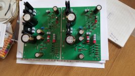
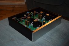
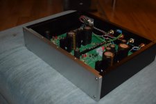
What I can see on the the boards looks quite good. Hook them up to the raw PSU, verify the regulators are giving the proper voltage, then attach the missing PSU resistors to energize the audio circuit.
Then, as always, take voltage readings and compare to the voltage map, if all is good, fantastic, of not, please report back.
I'm sorry if this was mentioned earlier, I didn't catch if this was Katie or Dad...? merely curious.
I've yet to build the raw PSU, I'm hoping to do that this evening.
I've rescued most of the parts from the scrap bin, including a nice pair of ELNA Cerafine 22000uF / 56V caps.
The transformer is a 0-24 0-24 50VA unit.
I've rescued most of the parts from the scrap bin, including a nice pair of ELNA Cerafine 22000uF / 56V caps.
The transformer is a 0-24 0-24 50VA unit.
Attachments
![20151019_115226[1].jpg](/community/data/attachments/477/477953-ccf3779b35702be183022025933256dc.jpg)
Last edited:
![20151019_120136[1].jpg](/community/data/attachments/477/477979-f1cbdb6aca9a0a159b50bf42da3a292b.jpg)
At last the Pearl 2 is finished
Well, after a bit of soldering the Pearl 2 is finished.
The PSU still needs a bit of work so I can't test it yet.
I've got a knurled nut coming for the ground post sometime this week.
Well, after a bit of soldering the Pearl 2 is finished.
The PSU still needs a bit of work so I can't test it yet.
I've got a knurled nut coming for the ground post sometime this week.
Attachments
Last edited:
- Home
- Amplifiers
- Pass Labs
- Building a Pearl 2