I remember vaguely that in an old Burr Brown application note it was mentioned that for filters with high Q, distortion will rise at the filter frequency and a low distortion buffer (opamp) therefore should be used.
Maybe the simple two get buffer is not optimal in this position. Has anyone tried it ?
Maybe the simple two get buffer is not optimal in this position. Has anyone tried it ?
:
")
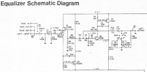
A question about the bass EQ:
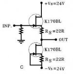
From the manual "... simple discrete Jfet circuits operated in single-ended Class A
without negative feedback. (The exception is the bass equalization circuit which requires
some feedback to get the curve needed)."
Has anyone an idea what type of circuit is used for the bass EQ ?
Attachments
It seems everyone misunderstood my question. I do know how to calculate and build Sallen & Key filters since 30 years. The question was why would a simple buffer be generally usable for such filters except for versions with high Q.
flg, what you have shown (where did it come from ?) adds some gain, OK but not a requirement for such a filter.
flg, what you have shown (where did it come from ?) adds some gain, OK but not a requirement for such a filter.
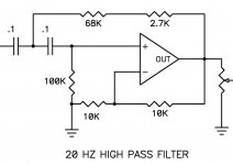
I thought you were refering to the "Q Bump" high-Pass. This is more than just a 20Hz High-Pass filter. It has a bump for added bass, just before rolloff. It is the bump that needs the extra gain. Just using buffers, you cannot build this type of filter.
I got this pic from an NP post, somewhere here???
I got this pic from an NP post
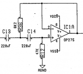
, somewhere here???No you are wrong. It´s just a high pass filter with a Q of about 2 (+6 dB "bump") and it can be built with a buffer. This kind of bass alignment is used in almost all active studio monitors, BTW. Attached such a filter (with a "bump" of about +3 dB at 43 Hz) from the Tannoy System 800A monitor. Notice that the opamp is wired as buffer (Av=1).
Attachments
Last edited:
No you are wrong. It´s just a high pass filter with a Q of about 2 (+6 dB "bump") and it can be built with a buffer. This kind of bass alignment is used in almost all active studio monitors, BTW. Attached such a filter (with a "bump" of about +3 dB at 43 Hz) from the Tannoy System 800A monitor. Notice that the opamp is wired as buffer (Av=1).
gk7, you asked; "Has anyone an idea what type of circuit is used for the bass EQ ? "
And I responded with a picture from NP himself.
There was only 1 question mark in the post I refrenced?
But you are right. I must not have understood the question and I should have just responded with NPs reasoning; "the bass equalization circuit ... requires some feedback to get the curve needed".
Yes, almost. My question was not so much about gain (which BTW might not be present in the LF channel of the B5, at least the manual does not mention any pass band gain), but why feedback would be beneficial for a filter with higher Q.
If we look at this in a more strict way, one could say that a Sallen & Key filter always needs some (positive) feedback to achieve a Q greater than 0.5 and that a buffer always has 100% (negative) feedback.
So, if gain (in the pass band) was chosen for the filter does not matter for the intended LF equalisation,
it´s just a design choice.
My question was about drawbacks / pitfalls when using a "B1 type" buffer with a Q of about 2.
It´s useage is apparently OK for the usual filters (like Butterworth Q=0.707 etc.).
the bass equalization circuit ... requires some feedback to get the curve needed.
Yes, every active filter with a Q > 0.5 requires (positive !) feedback. Don´t mix that up with the usual negative feedback.
Bass Alignment Filter Example
Thanks a lot for clarifying this, and yes building such a LF Eq
or bass alignment filter with a unity gain buffer is what I had
in mind.
I know from PM meanwhile that I´m not the only one interested in
such a thing and therefore I hope it´s not too much OT if I post
here how to calculate such a filter and an example for adjustable
frequencies.
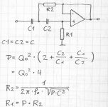
The attached hp_for_bass_alignment.jpg shows how to calculate the
resistor values for the case C1 = C2.
You can see that the resistor values decrease proportional with
frequency and actually the frequency values add up when paralelling
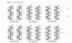
their corresponding resistor values. See the B5 manual where this
is used to adjust the crossover frequencies or the attached
bass_alignment-dip_switches.jpg from the Bowers & Wilkens bass
alignment filter.
If we calculate values for 2, 4, 8, 16 and 32 Hz and have them
wired so that we can switch them in paralell via dip switches
we can dial in any frequency between 2 and 62 Hz in 2 Hz steps.
Keep in mind that just because there is such a wide adjustment
range this does not imply that you should use all of it.
Values < 20 Hz and > 45 Hz do not really make sense IMHO.
Maximum boost occurs slightly above f and would be slightly
more than +6 dB for a Q of 2.
I have chosen Q = 1.92 (which results in a maximum boost of +6dB
and C1 = C2 = 100nF for the values given below:
2 Hz
R1=3055.774907 kOhm
R2=207.232999 kOhm
4 Hz
R1=1527.887453 kOhm
R2=103.616499 kOhm
8 Hz
R1=763.943727 kOhm
R2=51.80825 kOhm
16 Hz
R1=381.971863 kOhm
R2=25.904125 kOhm
32 Hz
R1=190.985932 kOhm
R2=12.952062 kOhm
Thanks a lot for clarifying this, and yes building such a LF Eq
or bass alignment filter with a unity gain buffer is what I had
in mind.
I know from PM meanwhile that I´m not the only one interested in
such a thing and therefore I hope it´s not too much OT if I post
here how to calculate such a filter and an example for adjustable
frequencies.
The attached hp_for_bass_alignment.jpg shows how to calculate the
resistor values for the case C1 = C2.
You can see that the resistor values decrease proportional with
frequency and actually the frequency values add up when paralelling
their corresponding resistor values. See the B5 manual where this
is used to adjust the crossover frequencies or the attached
bass_alignment-dip_switches.jpg from the Bowers & Wilkens bass
alignment filter.
If we calculate values for 2, 4, 8, 16 and 32 Hz and have them
wired so that we can switch them in paralell via dip switches
we can dial in any frequency between 2 and 62 Hz in 2 Hz steps.
Keep in mind that just because there is such a wide adjustment
range this does not imply that you should use all of it.
Values < 20 Hz and > 45 Hz do not really make sense IMHO.
Maximum boost occurs slightly above f and would be slightly
more than +6 dB for a Q of 2.
I have chosen Q = 1.92 (which results in a maximum boost of +6dB
and C1 = C2 = 100nF for the values given below:
2 Hz
R1=3055.774907 kOhm
R2=207.232999 kOhm
4 Hz
R1=1527.887453 kOhm
R2=103.616499 kOhm
8 Hz
R1=763.943727 kOhm
R2=51.80825 kOhm
16 Hz
R1=381.971863 kOhm
R2=25.904125 kOhm
32 Hz
R1=190.985932 kOhm
R2=12.952062 kOhm
Attachments
Thanks a lot for clarifying this, and yes building such a LF Eq
or bass alignment filter with a unity gain buffer is what I had
in mind.
I know from PM meanwhile that I´m not the only one interested in
such a thing and therefore I hope it´s not too much OT if I post
here how to calculate such a filter and an example for adjustable
frequencies.
The attached hp_for_bass_alignment.jpg shows how to calculate the
resistor values for the case C1 = C2.
You can see that the resistor values decrease proportional with
frequency and actually the frequency values add up when paralelling
their corresponding resistor values. See the B5 manual where this
is used to adjust the crossover frequencies or the attached
bass_alignment-dip_switches.jpg from the Bowers & Wilkens bass
alignment filter.
If we calculate values for 2, 4, 8, 16 and 32 Hz and have them
wired so that we can switch them in paralell via dip switches
we can dial in any frequency between 2 and 62 Hz in 2 Hz steps.
Keep in mind that just because there is such a wide adjustment
range this does not imply that you should use all of it.
Values < 20 Hz and > 45 Hz do not really make sense IMHO.
Maximum boost occurs slightly above f and would be slightly
more than +6 dB for a Q of 2.
I have chosen Q = 1.92 (which results in a maximum boost of +6dB
and C1 = C2 = 100nF for the values given below:
2 Hz
R1=3055.774907 kOhm
R2=207.232999 kOhm
4 Hz
R1=1527.887453 kOhm
R2=103.616499 kOhm
8 Hz
R1=763.943727 kOhm
R2=51.80825 kOhm
16 Hz
R1=381.971863 kOhm
R2=25.904125 kOhm
32 Hz
R1=190.985932 kOhm
R2=12.952062 kOhm
I'll own up to being the PM.
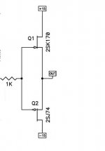
I'd posted before on feasibility of a bass boost with a unity gain buffer (2SK170/2SJ74).
I am new to all active OXs and OB design in general, so if my questions are foolish, my apologies.
You mention values from >20 and <45 don't make sense, I'm curious why you think that.
Would your calculation work like the 12dB version of the Xenover (attached)? Could the Rs and Cs just substitute into the design Grey put out? If not, can you help me understand how a unity gain buffer would be configured to work as a bass boost - schematic very welcome.
Attachments
Last edited:
You mention values from >20 and <45 don't make sense, I'm curious why you think that.
>20
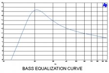
Such a filter can only extend the bass response by 1/2 an octave or so.
(Have a look at the attached bass_equalization_curve.jpg from the B5 manual.)
A filter with e.g. a 15 Hz bump would require a speaker thats already flat
to about 20 Hz. If you lower the frequency by 2 you need 4 times the excursion
or 4 times the cone area for the same SPL.
And then there is the question if there is something below 20 Hz on
a recording. But maybe for cinema effects that you can feel ... ;-)
<45
EQ will not make a bass monster out of a speaker that has no bass
to speak of, I think a subwoofer might be the better solution in such a case.
Well maybe one could extend a "mini monitor" to 50 Hz this way.
Would your calculation work like the 12dB version of the Xenover (attached)? Could the Rs and Cs just substitute into the design Grey put out? If not, can you help me understand how a unity gain buffer would be configured to work as a bass boost - schematic very welcome.
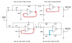
Yes, the 12 dB/octave high pass from the schematic attached should work,
C1 and C3 from this schematic are C1 and C2 in my calculation, R1 (calculated) is R8 (xenover) and R2 (calculated) becomes R6 (xenover).
It´s just a high pass with a higher Q which provides the "bump". If you would
use a Q = 0.707 for example you would get the well known second order Butterworth filter.
For some background information:
Sallen?Key topology - Wikipedia, the free encyclopedia
Q factor - Wikipedia, the free encyclopedia
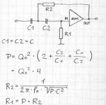
I have attached bass_alignment_with_buffer.jpg to clarify the connection to a unity gain (Av=1) buffer and two possible buffers with FETs (jfet_buffer.jpg and jfetfollower.jpg).
Attachments
- Status
- This old topic is closed. If you want to reopen this topic, contact a moderator using the "Report Post" button.
- Home
- Amplifiers
- Pass Labs
- B5 caught in the wild :)