I have run a single pair at 1.8A for a long time in the 5U chassis. I’ve moved on to 2 pairs of toshiba mosfets now though....dual pairs at 24v in the 5U chassis will do 2.5A, dual pairs at 32v (f5 turbo) will be about 1.9-2A.
My point was that bias is more important than biamping/triamping or whatever in a single chassis.
My point was that bias is more important than biamping/triamping or whatever in a single chassis.
I have run a single pair at 1.8A for a long time in the 5U chassis. I’ve moved on to 2 pairs of toshiba mosfets now though....dual pairs at 24v in the 5U chassis will do 2.5A, dual pairs at 32v (f5 turbo) will be about 1.9-2A.
My point was that bias is more important than biamping/triamping or whatever in a single chassis.
I guess I'll up the bias voltage to .7v or so and see how it goes. I'm in the 4U case and the heatsinks run at 119 deg F. The bodies of the mosfets are the same so I think I have good heat transfer.
It depends on your speakers but bias is very important on the F5. There is a dramatic difference between say 1A bias and 1.8A bias in the character of the amp. I run my amp pretty hot (55c) in order to get the most bias out of it. Bias is free (other than the electricity) so why not try it?
It depends on your speakers but bias is very important on the F5. There is a dramatic difference between say 1A bias and 1.8A bias in the character of the amp. I run my amp pretty hot (55c) in order to get the most bias out of it. Bias is free (other than the electricity) so why not try it?
I've been conservative up to this point because I don't have any speaker protection and don't want to sacrifice the JFETs in case something fails.
Biased it from .6v up to .7v and saw an increase of ~6deg F on the heatsinks after running an hour. Will see how it sounds and go from there. 😀
Biased it from .6v up to .7v and saw an increase of ~6deg F on the heatsinks after running an hour. Will see how it sounds and go from there. 😀
Should have more weight and sound more "liquid", but it depends on how demanding your speakers are.
F5 Cross Channel Ground Loop
Hi all – I finished a standard F5 build consistent with 6L6’s build guide a couple weeks ago. All looks pretty good – voltages are good, both channels biased without a sweat, and sounds great overall, but after much research I think I have a cross channel ground loop. Apologies for the length of this post, but I’m trying to explain as thoroughly as I can. Here’s where I am:
This is pretty much a stock build (pic attached at the end):
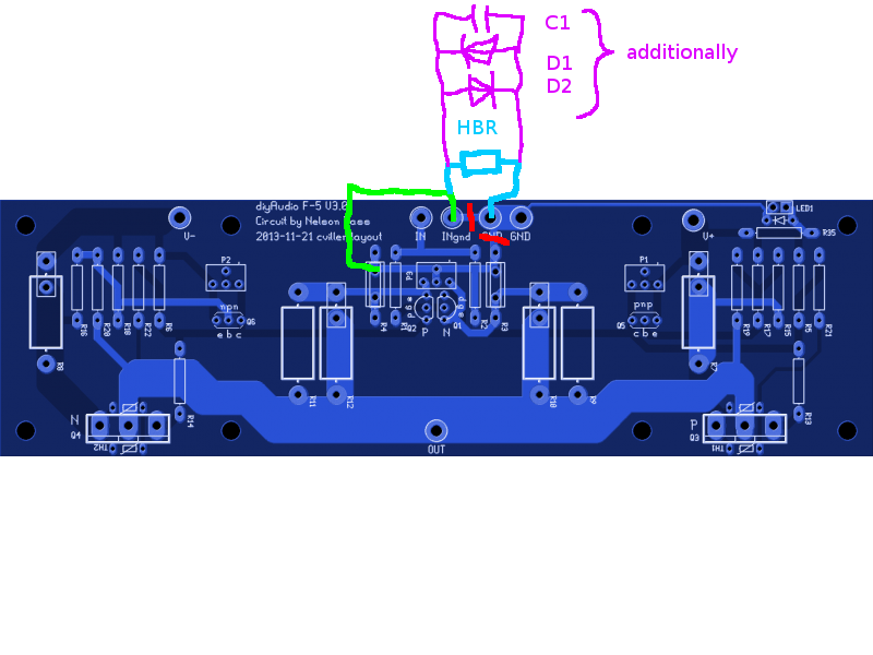
Reading this and D.Joffe’s paper on ground loops (link) leads me to believe that hum breaking resistors (HBRs) on the F5 could be a remedy to this issue.
The most comprehensive description of how to implement HBRs on the v.3 F5 boards appears to be in post #15333 of this thread (link), specifically following the modifications explained in this picture, which includes cutting the ground trace at the two red lines.
My issue is that I haven’t been able to find much further discussion of the utility of this modification to these boards (I have looked, but haven’t found much). Specifically, I don’t want to take a scalpel to my boards if this isn’t an effective/appropriate solution to this issue.
Mine wasn’t a perfect build, so let’s go through a couple things that went wrong along the way. I don’t think these are causing the issue since everything other than the hum under the scenarios I outlined above looks good, but I don’t want to ignore these:
Here's a picture of my build:

Hi all – I finished a standard F5 build consistent with 6L6’s build guide a couple weeks ago. All looks pretty good – voltages are good, both channels biased without a sweat, and sounds great overall, but after much research I think I have a cross channel ground loop. Apologies for the length of this post, but I’m trying to explain as thoroughly as I can. Here’s where I am:
This is pretty much a stock build (pic attached at the end):
- Universal 4U Chassis (Steel)
- DIY Audio Soft Start Board
- Antek AS-3218 transformer (18+18 @ 300va)
- Universal PSU with discrete diodes. 4x 15,000 uF caps + 5x .47/3w resistors per rail
- F5 boards w/matched NOS Toshiba JFETs
- Signal ground is connected to the chassis at the safety ground via CL-60
- Inputs shorted and/or empty
- One input connected to preamp / one input empty and/or shorted
- Two different preamps (one with an earth ground pin the other running off a two prong wall wart);
- A passive stepped attenuator;
- When cheater plugs are applied to F5 or earthed preamp (a very quick test I assure you).
Reading this and D.Joffe’s paper on ground loops (link) leads me to believe that hum breaking resistors (HBRs) on the F5 could be a remedy to this issue.
The most comprehensive description of how to implement HBRs on the v.3 F5 boards appears to be in post #15333 of this thread (link), specifically following the modifications explained in this picture, which includes cutting the ground trace at the two red lines.
My issue is that I haven’t been able to find much further discussion of the utility of this modification to these boards (I have looked, but haven’t found much). Specifically, I don’t want to take a scalpel to my boards if this isn’t an effective/appropriate solution to this issue.
Mine wasn’t a perfect build, so let’s go through a couple things that went wrong along the way. I don’t think these are causing the issue since everything other than the hum under the scenarios I outlined above looks good, but I don’t want to ignore these:
- The transformer does hum when the amplifier is on. It’s audible from about 4-6 inches when the lid is removed, but--as described--the amp is silent until both inputs are connected to a preamp.
- When I originally built the soft start board, I installed the electrolytic capacitor backwards, which rendered the board useless. Voltage was going straight through to the transformer without the soft start. I didn’t realize this was an issue until I fully biased the F5 and the 5w resistors on the soft start board started smoking. Once I fixed the capacitor, the board started functioning properly and everything resumed as normal. I only mention this to see if this could have damaged the transformer and/or PSU.
- When I built the PSU, I was not expecting to have to separate the diode and filter boards from each other to fix in the chassis. Remedying this required extensive desoldering, which I’m terrible at. A couple of pads required a lot of heat to desolder, which in turn indirectly melted a small part of the plastic sheath off two of the capacitors (one per channel). Could this indirect heat (enough to melt a bit of the plastic) have damaged these filter caps?
Here's a picture of my build:
You placed the transformer in the ground loop, which exists when you plug the interconnects in the preamp.
You should place the transformers to the front side and the psu to the back, as you can see in the FW amps.
BTW nice amp🙂
You should place the transformers to the front side and the psu to the back, as you can see in the FW amps.
BTW nice amp🙂
Last edited:
Also the F5 has soft start designed into the power supply with the 2 CL60s, so no need for soft start board.
I have use this board in many less than ideal implementations without hum, so I think you can get it fixed easily.
A few observations based on your pictures:
- You seem to use small gauge wire from diode board to filter bank on your psu and also for your speaker outputs. I would beef that up.
- I can't exactly see what happens with your ground NTC. It looks like you are grounding directly - what is the purple wire?
- The amp is high frequency, so the output wires behind the board may be leading to some kind of oscillation - and I would also not put them through the bottom plate, they could be picking up something from the cabinet.
My best guess is that it is something with your ground wiring. You can try and play music from a phone running off a battery - one channel at a time with the other shorted and then with both if all goes well.
I have use this board in many less than ideal implementations without hum, so I think you can get it fixed easily.
A few observations based on your pictures:
- You seem to use small gauge wire from diode board to filter bank on your psu and also for your speaker outputs. I would beef that up.
- I can't exactly see what happens with your ground NTC. It looks like you are grounding directly - what is the purple wire?
- The amp is high frequency, so the output wires behind the board may be leading to some kind of oscillation - and I would also not put them through the bottom plate, they could be picking up something from the cabinet.
My best guess is that it is something with your ground wiring. You can try and play music from a phone running off a battery - one channel at a time with the other shorted and then with both if all goes well.
Thanks all! To answer a couple of these questions:
1. Unfortunately the diode output pads and the filter bank input pads are quite small, and I could not get thicker gauge wire in there (I did try). If they can fit .25 tabs, I can try those and attach the thicker gauge wire.
The purple wire is the transformer shield ground. The signal ground is the white wire, routed under the bottom plate, connected to the safety ground through the CL-60.
Since it's the easiest to start with, I will start by moving the signal wires in front of the amp boards and will bring everything except the AC wires (which run between the IEC/switch to the soft-start) above the bottom plate. I used the method I did because I thought it would help keep everything well separated.
I thought with an F5 build, a CL-60 or a soft-start board should be used.
I would love to rearrange to have the transformer toward the front, but I simply could not find the space to mount the filter bank on the bottom plate with the discrete rectifier boards. It may fit if I mount the transformer vertically. Can anyone recommend an L bracket for an Antek 300va? I'll look at some other layout options. It also might work if I ditch the soft start.
I'm assuming you built the standard F5 power supply per Nelson's drawing. If you didn't and added a soft start board then that's different.
I'm assuming you built the standard F5 power supply per Nelson's drawing. If you didn't and added a soft start board then that's different.
Yes -- that's correct -- soft start board in lieu of the CL-60 (as drawn in the original PSU schematic)
I'm with @rookakoma. Presuming you're not using a dual mono power supply you have a big 'C' from the left input ground to the left channel board to the capacitor bank ground to the right channel board to the right input ground.
If your pre-amp also doesn't have a dual mono supply, then it will connect the left channel ground and the right channel ground through its PSU. That forms a loop. Your transformer is inside that loop.
You can test this theory by cutting one of the capacitor-bank-to-channel ground wires and replacing it with a longer wire that runs alongside the other channel ground wire, continuing along the back panel and then to the channel whose ground was cut. That will reduce the area inside the loop (and more importantly remove the transformer from it).
I'm with @rookakoma. Presuming you're not using a dual mono power supply you have a big 'C' from the left input ground to the left channel board to the capacitor bank ground to the right channel board to the right input ground.
If your pre-amp also doesn't have a dual mono supply, then it will connect the left channel ground and the right channel ground through its PSU. That forms a loop. Your transformer is inside that loop.
You can test this theory by cutting one of the capacitor-bank-to-channel ground wires and replacing it with a longer wire that runs alongside the other channel ground wire, continuing along the back panel and then to the channel whose ground was cut. That will reduce the area inside the loop (and more importantly remove the transformer from it).
Yeah, I see that now. Instead of cutting a wire, couldn't you just move the preamp in front of the power amp and run the phono cables separate on each side?
Yeah, I see that now. Instead of cutting a wire, couldn't you just move the preamp in front of the power amp and run the phono cables separate on each side?
Yep; good idea.
Yep; good idea.
I'll give these both a try! Thanks for the explanation on how the signal ground wires are in the loop, and how moving the preamp could help. I actually understand it now.
If you have the time and interest, the very same topic has been discussed starting here:
First Watt F7 review
First Watt F7 review
Wow — that was easy — you guys nailed it on the transformer being in the loop. Tested with the preamp routed to the front and noticed a huge immediate difference. Rerouted one of the F5 signal grounds to avoid making a loop with the transformer as a more durable solution. Noticeably quieter in all configurations. One channel a little louder than the other, but the quiet channel requires an ear pretty much directly on the speaker to hear anything. I’ll mess around a bit more trying to get both channels equal (they were equal when the pre was in front), but this is pretty close for a newb like me.
I'm assuming you built the standard F5 power supply per Nelson's drawing. If you didn't and added a soft start board then that's different.
I use that soft start on my BA3 amp, like in the 6L6 BA3 build guide. Dead silent.
Russellc
- Home
- Amplifiers
- Pass Labs
- F5 power amplifier