Hi,
I have seen a few speaker protection circuits, but they all seem to be designed for a particular power amp, or just don't seem very flexible.
I have been searching the past week or so and found several designs which look workable, and some that kinda scare me.
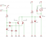
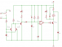
Anyway, based an what I have learned I have come up with this (this is just the basic schematic, there will be slightly more to it).
Does this look sane?
In particular I am wondering about the zener diodes and the Schottky's I have to prevent the zeners from shorting each other out. I am not sure if what I am doing there is necessary. The idea was to protect T1 and T2 from full power amp rail voltages at the input.
Comments welcome.
Cheers!
Russ
I have seen a few speaker protection circuits, but they all seem to be designed for a particular power amp, or just don't seem very flexible.
I have been searching the past week or so and found several designs which look workable, and some that kinda scare me.
Anyway, based an what I have learned I have come up with this (this is just the basic schematic, there will be slightly more to it).
Does this look sane?
In particular I am wondering about the zener diodes and the Schottky's I have to prevent the zeners from shorting each other out. I am not sure if what I am doing there is necessary. The idea was to protect T1 and T2 from full power amp rail voltages at the input.
Comments welcome.
Cheers!
Russ
Attachments
Nice and simple! Have you tested it? The last one I did I connected it to my amp and put a signal gen through it at full taps and tested it down to around 10Hz, where it would trigger.
Yours is a bit different to what I have used in the past, but I can't see why it wont work.
Yours is a bit different to what I have used in the past, but I can't see why it wont work.
I looked at the relay you're using (Future Elec's site) and noted that it's contacts are only rated for 24 VDC. The JQX115's they list are DPDT and rated for 125 VDC. The ability to break more than 24 VDC is very important. I'm working on a similar design and will give the JQX115 serious consideration.
I thnk the Futurlec specs are a bit unclear the way they summarized them. Here are the specs from the Omron G5LB dtasheet (same form factor relay):
Rated load: 10 A at 120 VAC; 8 A at 30 VDC & 10A at 250 VDC
Rated carry current: 10 A
Max. switching voltage: 250 VAC, 125 VDC (30 VDC when UL/CSA standard is applied)
Max. switching current: AC: 10A; DC: 8A
Max. switching capacity: 1,200 VA, 240 W & 2,500 VA
Min. permissible load: 100 mA at 5 VDC
So, you can switch more than 25/30VDC, just with less than 10A current. Although, the first line does strike me as strange: 8A@30VDC and 10A@250VDC?
Anyway, this is the relay we use on the RevC Monoblocks for speaker protection (Siemens version).
Hi,
do you realise you have 4V across the BE junction of t3?
The grounding of the speaker output is far better. It will help blow the amplifier fuse if the arc across the contacts refuses to extinguish. You need rail fuses to take advantage of this.
How can you latch the protection ON after activation? You don't want it chattering ON OFF ON with one supply rail sending offset to the speaker.
I'm not sure the Zeners are quite right.
I think C2 will delay ON till it's too late (or over current T1 and/or T2).
D1 slows down the release of the relay.
You can speed up the release by running it at lower voltage with a dropper resistor and then add a cap from top of relay coil to T3 emitter. The 24V on the extra cap prior to T3 closing fires the relay and then voltage falls to some lower value (above guaranteed hold in V).
AndrewT said:Hi,
1) do you realise you have 4V across the BE junction of t3?
2) The grounding of the speaker output is far better. It will help blow the amplifier fuse if the arc across the contacts refuses to extinguish. You need rail fuses to take advantage of this.
3)How can you latch the protection ON after activation? You don't want it chattering ON OFF ON with one supply rail sending offset to the speaker.
4) I'm not sure the Zeners are quite right.
5) I think C2 will delay ON till it's too late (or over current T1 and/or T2).
6) D1 slows down the release of the relay.
You can speed up the release by running it at lower voltage with a dropper resistor and then add a cap from top of relay coil to T3 emitter. The 24V on the extra cap prior to T3 closing fires the relay and then voltage falls to some lower value (above guaranteed hold in V).
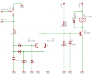
1) I really hadn't finalized the resistor values yet, thanks for spotting that that was pretty high. I have changed it.
2) So at least I got that part right?
")
3) I am not sure how do accomplish this without defeating one of my design goals which is to make the circuit self resetting. I am open to suggestions.
4) Me either, the way I have them they should protect T1 and T2 from VBE > 6V. That was the idea.
5) It could be I will have to test. I have changed the cap and resistor values.
6) I believe I have understood you here, and it makes a lot of sense. Thanks for the excellent suggestion. I hope I have implemented it correctly. I will have to calculate R4 for the correct voltage drop.
Thanks very much for all the input so far!
Attachments
Hi,
try breadboarding one that works.
When you understand how it detects and hold, and closes/opens the relay then think about redesigning/improving the circuit.
The r2/r3 divider will either prevent t3 switching on or risk killing it if the supply voltage rises a little.
You have implemented C3 correctly. You can now run at more than 24Vdc and adjust R4 to hold in under all normal operating conditions.
That 24V supply can come from ONE diode on the main PSU rectifier bridge with just a tiny bit of smoothing to give near instant drop out on loss of mains voltage.
But, I fear the circuit, as is, is struggling to work.
AndrewT said:Hi,
do you realise you have 4V across the BE junction of t3?
No, he hasn't.
There's 0.6V, limited by the VBE. Under these conditions, about 0.1mA is available to turn on the transistor. Assuming a (generous) worst-case HFE of 50, that only results in 5mA to drive the relay coil.
I haven't looked up the relay, but I would determine the coil current, then double it. Divide that by the worst-case HFE to find the base current, then double that to be sure. You're trying to saturate the transistor! I would suggest that a value around 22K would be a good starting point - 470K will not work! Remember - you're *not* trying to make a potential divider here, you are providing T3 with base current...
R3 doesn't play that much of a role in this calculation, as it only steals 12uA from the contribution of R2.
C2 provides a power-on delay, but in the event of a DC fault, one of the two input transistors will have to discharge it. Maybe fine for T1, but in the case of T2 doing this, the only means it has to sink current is via the input 100K (R1). I would suggest that this is a problem... For that reason, move the on-delay elsewhere - perhaps add another transistor after T3. This also makes it easier to implement the latch:
Another transistor is needed, forming a simple bistable latch with T3. Some sort of power-up reset is needed, probably a series RC combination.
BUT, do you need the latch? If this circuit triggers, the fault condition will almost certainly persist once the speaker has been disconnected. In fact, the DC fault voltage will probably rise once the OPS has been relieved of supplying many amps to the poor voice coil. You are correctly sampling before the relay contacts
For what it's worth, I implemented this DC-detect circuit in my quad LM4780 amp, only I interfaced it to a PIC (overkill, but the PIC was there doing other things). During testing, I found it works well, but you need to avoid trying to pull too much current from the collectors of the transistors if you want the detection thresholds to remain symmetrical (although C1 helps, of course). Which is what could happen with this simple circuit if you stick with 3 transistors (so perhaps a Darlington would be better for T3?)
Mark
No worriesAndrewT said:Thanks Mh,
I didn't see the constant current through r3!
BTW, you're right about the zener diodes - as shown they only work as normal diodes anyway. I'd omit them and just connect the base of T1 to the emitter of T2. No worries about the 6-7V reverse-VBE damage as the other transistor clamps this to 0.6V.
Another BTW - much as the power-saving relay scheme is a good idea, it might not function in this circuit because C2 causes T3 to turn on slowly. He could fix this by adding another transistor to make a schmitt trigger... I've used current sources with relays, but this has been more about varying supply voltages than saving power... (a good idea if using the half-wave/small C scheme you rightly suggested)
Douglas Self did an article about relay release speed, conclusions were pretty much common sense IIRC. Don't forget the delay caused by the input RC filter (I guess about 65ms currently)
Cheers,
Mark
Excellent feedback Mark and Andrew!
I very much appreciate your thoughtful advice.
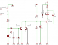
Here is what I have now based on your inputs.
Any further feedback is greatly appreciated.
R4 is there to adjust the sensitivity of the DC protection.
:EDIT: schematic was screwed up. Fixed.
I very much appreciate your thoughtful advice.
Here is what I have now based on your inputs.
Any further feedback is greatly appreciated.
R4 is there to adjust the sensitivity of the DC protection.
:EDIT: schematic was screwed up.
Fixed.Attachments
Hi Russ,
This looks better than before, and will probably work ok. Comments?
R4 probably won't affect the sensitivity in any desireable way (because it depends on the HFE of the transistors, and will affect the turn-over frequency of the input filter). It's better to have lower values here because the input transistors will need some current - 100K is as high as I'd go.
R3 probably isn't needed.
R7 definitely not needed.
The circuit doesn't self-reset very quickly because there's nothing to discharge C2 (apart from the intrinsic diodes in the op-amp - not good!). Add an 1n4148 in parallel with R2, pointing "up"...
C3 would probably be better if it was 100uF, perhaps more. Testing required...
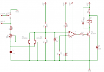
The circuit still suffers from having to discharge the power-on delay cap via the input transistors (and R1). This morning I quickly sketched up a circuit that uses a PNP emitter follower after the input pair to get around this problem. It also uses a current source to drive the relay. I've hacked around your latest diagram to show you the idea...
There's an optional DC-fault LED indication, and longer power-on delays are possible because you can use large values of C with no issues. Whether it's better for your application is obviously for you to decide...
Hope this helps,
Mark
This looks better than before, and will probably work ok. Comments?
R4 probably won't affect the sensitivity in any desireable way (because it depends on the HFE of the transistors, and will affect the turn-over frequency of the input filter). It's better to have lower values here because the input transistors will need some current - 100K is as high as I'd go.
R3 probably isn't needed.
R7 definitely not needed.
The circuit doesn't self-reset very quickly because there's nothing to discharge C2 (apart from the intrinsic diodes in the op-amp - not good!). Add an 1n4148 in parallel with R2, pointing "up"...
C3 would probably be better if it was 100uF, perhaps more. Testing required...
The circuit still suffers from having to discharge the power-on delay cap via the input transistors (and R1). This morning I quickly sketched up a circuit that uses a PNP emitter follower after the input pair to get around this problem. It also uses a current source to drive the relay. I've hacked around your latest diagram to show you the idea...
There's an optional DC-fault LED indication, and longer power-on delays are possible because you can use large values of C with no issues. Whether it's better for your application is obviously for you to decide...
Hope this helps,
Mark
Attachments
Not wishing to undermine all your hard work, but Velleman have a kit for this.
Part # K4700, the assembly manual with schematic are available for download on their website.
www.velleman-kit.com
Paul
Part # K4700, the assembly manual with schematic are available for download on their website.
www.velleman-kit.com
Paul
Russ White said:Wow thanks Mark, those are some good pointers.
What would you think about something like this?
Hi Russ,
That looks pretty good. IC1 will ensure the relay is snapped on quickly, allowing the power-saving scheme to work. I might have added another transistor to my last circuit to achieve that, but it's personal preference thing. I like transistors!
Now, C2/R4 can be lower/higher respectively. I chose those values in my circuit to ensure sufficient base current in the relay drive transistor. Certainly 22u and 100K would be where I'd start now...
Regarding IC1: Watch the total supply voltage (assuming it's fed from a half-wave rectified version of the main transformer). Obvious, I know...
Be sure your chosen device is happy to have its inputs close to the supply rails (I've been caught out in the past with the TL08x devices). It might be worth trying a resistor (1-10K, say) at the non-inverting input of the op-amp so that the input doesn't see such a low impedance close to the rail (some devices can be funny about this)
It might help to add a feedback resistor to IC1 to give it schmitt action. Say 100K-1M between out and +in, (note you'll also need to add the input resistor mentioned above). This will ensure the o/p changes state cleanly with no spurious transitions (perhaps caused by the unregulated supply). Any funny business happening at this time might affect the operation of the power-save relay drive circuit.
Time to start bread-boarding
Mark
soundtech said:Not wishing to undermine all your hard work, but Velleman have a kit for this.
Part # K4700, the assembly manual with schematic are available for download on their website.
www.velleman-kit.com
Paul
Yes, I know this kit well. While this might solve the problem, no-one here would learn anything from just buying a kit.
Also, it's somewhat complicated, don't you think? Just look at all those electrolytic capacitors waiting to dry out!
I don't know if Russ is planning to add this to his product range, but it would certainly be a compact and economical alternative to the Vellemen offering
Mark
soundtech said:Not wishing to undermine all your hard work, but Velleman have a kit for this.
Part # K4700, the assembly manual with schematic are available for download on their website.
www.velleman-kit.com
Paul
This is not about "obtaining" a solution, but rather designing one. There are more than a couple designes I could directly copy, but I wouldn't learn anything that way.
This is the joy for me, the journey, not just the destination. t has been very fun so far.
mhennessy said:
Hi Russ,
Now, C2/R4 can be lower/higher respectively. I chose those values in my circuit to ensure sufficient base current in the relay drive transistor. Certainly 22u and 100K would be where I'd start now...
Regarding IC1: Watch the total supply voltage (assuming it's fed from a half-wave rectified version of the main transformer). Obvious, I know...
Be sure your chosen device is happy to have its inputs close to the supply rails (I've been caught out in the past with the TL08x devices). It might be worth trying a resistor (1-10K, say) at the non-inverting input of the op-amp so that the input doesn't see such a low impedance close to the rail (some devices can be funny about this)
Time to start bread-boarding
Mark
Hi Mark,
Once again very good input! Thanks!
I was thinking I might add an additional zener on the non-inverting opamp input to limit the voltage there to below the rail voltage, maybe something like a 18V zener.
I will add the resistors as you say, I was actually thinking the same thing, just had not fleshed it out that far yet.
I will probably use something like a LF411 for the circuit (since I have a bunch of them and they are relatively cheap).
Cheers!
Russ
- Status
- This old topic is closed. If you want to reopen this topic, contact a moderator using the "Report Post" button.
- Home
- Design & Build
- Parts
- A simple speaker protection circuit