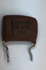
.17 = 0.17 uF = 170nF capacitor an unusual value with a 100V rating
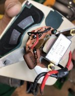
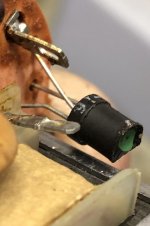
And think ive found the6800pF = 6.8nF = 0.0068uF disc capacitor radial styles. Also looking for a number for this black transistor that isnin photo on left but it says g-16 on it and has a green dot of paint on top ?
And think ive found the6800pF = 6.8nF = 0.0068uF disc capacitor radial styles. Also looking for a number for this black transistor that isnin photo on left but it says g-16 on it and has a green dot of paint on top ?
Attachments
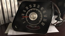
...a 1968 ford tachometer ....
Obviously: check the naked meter movement with a very small current. 12V through 47K will be safe.
By total chance I ran across this article. While it is 10 years later, Ford never rushed into new ideas (or did and stumbled). The exact parts available would have changed, and this may not be "your" tach, but the ideas are general.
And I am very sure there are Mustang Tach Expert Restorers. While I agree with DIY in general, I was fond of my several '67s, and think it is time for them to be done right.
Attachments
Thanks for posting ")
When I started with Electronics, late 60´s, I used to buy "100 Transistor circuits" type books (no Internet way back then ) and this kind of tachometer circuit was popular .
Similar to "Dwell angle meter", whatever that means.
You show a PNP Germanium transistor type, this one apparently has an NPN Silicon unit, working principle is the same.
Now to:
If anything, as suggested above, first suspect would be a dust caked, rusty meter movement, or corrosion open moving coil winding ... or both.
Shotgunning electronics parts will not help you if "mechanicals" are bad.
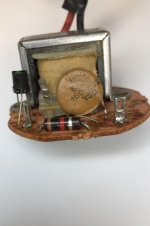
And what about the choke or transformer shown in the first picture?
Agree with letting a specialist do his job, specially because of the unavailable mechanical parts.
When I started with Electronics, late 60´s, I used to buy "100 Transistor circuits" type books (no Internet way back then ) and this kind of tachometer circuit was popular .
Similar to "Dwell angle meter", whatever that means.
You show a PNP Germanium transistor type, this one apparently has an NPN Silicon unit, working principle is the same.
Now to:
Why do you think those parts are bad?.17 = 0.17 uF = 170nF capacitor an unusual value with a 100V rating
And think ive found the6800pF = 6.8nF = 0.0068uF disc capacitor radial styles. Also looking for a number for this black transistor that isnin photo on left but it says g-16 on it and has a green dot of paint on top ?
If anything, as suggested above, first suspect would be a dust caked, rusty meter movement, or corrosion open moving coil winding ... or both.
Shotgunning electronics parts will not help you if "mechanicals" are bad.
And what about the choke or transformer shown in the first picture?
Agree with letting a specialist do his job, specially because of the unavailable mechanical parts.
"Dwell angle meter", whatever that means.
In an old school automotive ignition system with contact breaker(s) the dwell angle, measured either in degrees or as a percentage, tells you how long the contact is closed w.r.t. a full revolution of the distributor shaft. It has to be adjusted according to the manufacturer's specs.
Best regards!
Apologies. It was late, I did not note the large iron coil on your unit, nor the 2-wire interface. I suspect it is not the same circuit. Tracing would help (not that many parts).
AGREE that these caps are not the most likely failures. However the disk is probably non-critical and not such an odd size. The 0.17uFd is tight tolerance and should be near that value for calibration. A 0.15u would "work" (IF that is actually the fault) but read low(?). You can easily assemble 0.17 out of several smaller values parallel.
Dwell is like duty-cycle. The coil needs time to fill with flux. At low RPM the time is always ample. If you set the break-angle right you have good spark. But if the dwell is short the spark goes weak at high RPM. Long dwell puts more heat in the coil than it was designed for. Dwell also reflects the break geometry of the points-cam. Dwell was never very critical, but a dwell-meter is just an averaging volt meter and cheap, and an Added Feature for 13-in-1 test-sets. (You'd figure dwell would matter in high-RPM racing but in fact if your spark goes weak you find a hotter coil and accept shorter points-life.)
Cool, that´s something.
Please apply some current to it , I would suggest 50 to 100 uA (micro Amperes) as a safe starting value and check whether needle moves, at least 5 or 10% of full scale.
If it does, then double current and check whether it moves about twice as much.
The cherry on the cake is to increase current until needle reaches full scale, that will tell us a lot about it and help future troubleshooting.
Don´t tell you to straight measure continuity or coil resistance because it´s very easy to damage or destroy such delicate wire and test current can easily be way too high, but values I suggested should be reasonably safe.
Only once you know meter actually reacts to current can you go on with the "electronic" part, but not otherwise.
EDIT: if coil is open, no electromechanical movement at all, the ball stops there unless you can replace/repair meter coil, it´s useless to try to "repair" the electronic area which as far as I know may be working perfectly well ... and we have NO way to check.
Last edited:
Cool, that´s something.
Please apply some current to it , I would suggest 50 to 100 uA (micro Amperes) as a safe starting value and check whether needle moves, at least 5 or 10% of full scale.
If it does, then double current and check whether it moves about twice as much.
The cherry on the cake is to increase current until needle reaches full scale, that will tell us a lot about it and help future troubleshooting.
Don´t tell you to straight measure continuity or coil resistance because it´s very easy to damage or destroy such delicate wire and test current can easily be way too high, but values I suggested should be reasonably safe.
Only once you know meter actually reacts to current can you go on with the "electronic" part, but not otherwise.
EDIT: if coil is open, no electromechanical movement at all, the ball stops there unless you can replace/repair meter coil, it´s useless to try to "repair" the electronic area which as far as I know may be working perfectly well ... and we have NO way to check.
Attachments
Images aligned, one mirrored, for possible circuit tracing (not tonight!).
This is a "series" tach, not simple parallel like the one above. It works on full spark-coil current, tapping a small amount via the transformer. There seems to be no 12V/Gnd feed to this tach. There was a no-transistor tach before this, but used a costly meter to get the right action.
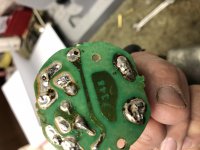
You seem to have cut-off the 3rd leg of the transistor(?) solder-side.
I do note at least one no-go solder joint.
This is a "series" tach, not simple parallel like the one above. It works on full spark-coil current, tapping a small amount via the transformer. There seems to be no 12V/Gnd feed to this tach. There was a no-transistor tach before this, but used a costly meter to get the right action.
You seem to have cut-off the 3rd leg of the transistor(?) solder-side.
I do note at least one no-go solder joint.
Attachments
Last edited:
I removed one resistor and the 17-100 capacitor in second photo to test them.
This tach from what i am told has no ground wire. Inask a guy that has worked on this year of car and he runs a auto shop, he says no ground even in dash housing where its installed.
There is a printed circuit board that is surronding this when installed in the dash and i purchased a new circuit board from him and its being shipped to me right now.
"The coil" means the meter moving coil which is inserted inside a magnet and attached to the meter needle.
When current passes through a coil submerged inside a magnetic field, said coil twists, and moves the needle.
There is a weak spring which resists "electrical push" and returns needle to zero wnen no current is passing.
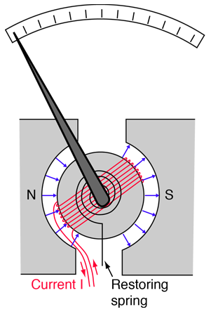
You must have somewhere 2 terminals to which the coil wire (which is hair thin) is soldered, just look at it with a loupe and under good light.
needle might not move because various reasons.
In due order:
1) caked/rusted/bent .... you already discarded this
2) open coil ... this is what I am trying to check.
3) bad electronics: can´t be checked until 1 and 2 are tested and discarded.
4) poor/missing connection to a working car ignition system
So far I am focusing on "2" , since it is both very important and quite likely.
It is also a deal breaker unless somebody can rewind or replace it.
When current passes through a coil submerged inside a magnetic field, said coil twists, and moves the needle.
There is a weak spring which resists "electrical push" and returns needle to zero wnen no current is passing.
You must have somewhere 2 terminals to which the coil wire (which is hair thin) is soldered, just look at it with a loupe and under good light.
needle might not move because various reasons.
In due order:
1) caked/rusted/bent .... you already discarded this
2) open coil ... this is what I am trying to check.
3) bad electronics: can´t be checked until 1 and 2 are tested and discarded.
4) poor/missing connection to a working car ignition system
So far I am focusing on "2" , since it is both very important and quite likely.
It is also a deal breaker unless somebody can rewind or replace it.

that would be inside the +80%/-20% tolerance range, wouldn't it?The small tan ceramic disc cap that says 6800 on it so i believed this to be a 6800pF = 6.8nF = 0.0068uF, but when testing this with my BK precision meter set on capacitance it tests at 5.8
Yes it would be, but thought it would be closer, guess not an issue.that would be inside the +80%/-20% tolerance range, wouldn't it?
- Status
- This old topic is closed. If you want to reopen this topic, contact a moderator using the "Report Post" button.
- Home
- Design & Build
- Parts
- Looking for these parts