I just use PVC covered 22AWG Solid core tinned copper hook up wire. The only time I've had to use better wire was from the phono RCA input to the grid of the input tube where I used a shielded beldon 22AWG stranded wire. Granted I don't need to run RF but the results are plenty good.
I just use PVC covered 22AWG Solid core tinned copper hook up wire. The only time I've had to use better wire was from the phono RCA input to the grid of the input tube where I used a shielded beldon 22AWG stranded wire. Granted I don't need to run RF but the results are plenty good.
Ditto (only my 22 AWG shielded is Lake rather than Belden).
In reality I probably don't need the shielding anymore. It was picking up RF due to me mistakenly using a 22K resistor instead of a 100R!
How is it to work with? The Belden is rigid but not in a good way, it doesn't stay where you put it, it stays coiled or however it was")
How is it to work with? The Belden is rigid but not in a good way, it doesn't stay where you put it, it stays coiled or however it was
Last edited:
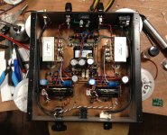
What? It contains a buffer, a line stage, a phono stage, a headphone stage, and a 6550 output stage with regulated screens. Oh and level meters... 22 tubes total. 9 inputs switched by relay, line out, 4 buffered outputs.
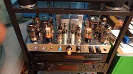
Here's the topside...
Here's the topside...
Attachments
Last edited:
At microwave frequencies you are hard pressed to keep the signal IN a wire!
In all signals I thought the signal travelled through the dialectic.
We worry about signal propagation on high speed digital designs, especially for the high speed interfaces such as DDR3, as depending on the PCB build you get different signal propagation depending on the dielectric used between the copper foils and cater for the sections that are microstrip (surface layers) and stripline (inner layer, preferably between two return paths). So for timing budgets we have to know the true signal transmission time from preferably die to die (some IBIS files include data withing the chip including bonding wires) so that we can get all the signals at the right place and more importantly at the right time, often down to 0.25mm difference in signal lengths (approx 2ps) and can be shorter for critical diff pairs. For domestic Audio signals I don't think signal speed is much of an issue if the correct cables are used... As specified for the interface.
In all signals I thought the signal travelled through the dialectic.

Yours is a much simpler design. Nice.
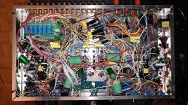
Here's a recent pic of the underside of mine... the red wires are the Belden wire...
agreed.
That mess of unpaired wiring looks ideal for emitting and receiving emi.
agreed.
That mess of unpaired wiring looks ideal for emitting and receiving emi.
Except that the entire chassis is ground (signal and power) and made of aluminum. No issues here, but it's not a radio...
Last edited:
Haha, I thought it was a really good joke
The first time someone laughs at on of my puns, it was completely dyslexic, gutted.
Except that the entire chassis is ground (signal and power) and made of aluminum. No issues here, but it's not a radio...
Except all the magnetic fields round the wires inside the box will couple with all the other wires inside the box, no return current paths seem to have been catered for, as for neatness and signal flow, isolation between sections, non apparent. So you will have internal interference.
The chassis is the current return path. Sure the magnetic fields interact, however it's not a rail gun. It's a tube amp. The currents, and therefore the magnetic fields coming off wires running DC in opposing direction are tiny compared to even the signal. Why should I isolate between sections? They are all working on the same signal. When you wire something so complex point to point this is what it looks like. And for the record it's still neater than the chassis wiring of my old RCA colour television. I also find running the wiring like this reduces capacitive coupling and reduces stray magnetic fields because it's so random.
- Status
- This old topic is closed. If you want to reopen this topic, contact a moderator using the "Report Post" button.
- Home
- Design & Build
- Parts
- Chassis wire