Here are some voltage noise measurements I made of a few transistors, using an amplifier circuit similar to the one published on syn08's "Low noise designs" web site, feeding a spectrum analyzer. The base of the transistor is grounded (source resistance = zero), and the gain of the common emitter transistor stage is high enough so the circuit is essentially measuring only the transistor voltage noise. The amplifier circuit has a gain of one million, so with 1 volt full scale, 1mv or -60dB is equivalent to 1nV. Note that noise values stated below are /square root(Hz) at 1KHz.
2N4401 #1 (old 1970's? Motorola, gold leads)
0.8nV @ 1mA, 0.8nV @ 10mA (high 1/f flicker noise at 10mA)
2N4401 #2 (newer Motorola, "928" date code)
0.63nV @ 1mA, 0.45nV @ 10mA
MAT02 (early 1990's)
0.7nV @ 1mA, 0.5nV @ 10mA
ZTX690B
0.6nV @ 1mA, 0.38nV @ 10mA
ZTX1051A
0.56nV @ 1mA, 0.32nV @ 10mA
ZTX849
0.5nV @ 1mA, 0.21nV @ 10mA
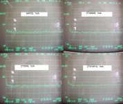
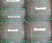
In the spectrum analyzer images above the low frequency spike at around 120Hz is power supply noise and not from the transistor. Also note the frequency scale is linear and not log.
I did not include a picture of the MAT02 at 10mA because I blew out two of them and did not want to risk any more (these parts are a bit delicate and 10mA is about the max recommended current anyway), so I included pictures of some 2N4401's at 10mA instead. The 2N4401 is one of the best values for low voltage noise but as the measurements indicate there is some wide variability - for parts with high flicker noise at high current you should parallel devices instead of running a single part.
Zetex (Diodes Inc) seem to be a virtually unknown source for low noise parts as they do not publish any noise specs, although they do have a design note (DN11) recommending their parts for low noise preamps. The ZTX849 is a very low noise part indeed but comes at a price (other than the cost between US$1-$2 ea), very high capacitance (>1000pF input as can be seen from the Spice model) which suggests that it would best be used in a cascode circuit.
2N4401 #1 (old 1970's? Motorola, gold leads)
0.8nV @ 1mA, 0.8nV @ 10mA (high 1/f flicker noise at 10mA)
2N4401 #2 (newer Motorola, "928" date code)
0.63nV @ 1mA, 0.45nV @ 10mA
MAT02 (early 1990's)
0.7nV @ 1mA, 0.5nV @ 10mA
ZTX690B
0.6nV @ 1mA, 0.38nV @ 10mA
ZTX1051A
0.56nV @ 1mA, 0.32nV @ 10mA
ZTX849
0.5nV @ 1mA, 0.21nV @ 10mA


In the spectrum analyzer images above the low frequency spike at around 120Hz is power supply noise and not from the transistor. Also note the frequency scale is linear and not log.
I did not include a picture of the MAT02 at 10mA because I blew out two of them and did not want to risk any more (these parts are a bit delicate and 10mA is about the max recommended current anyway), so I included pictures of some 2N4401's at 10mA instead. The 2N4401 is one of the best values for low voltage noise but as the measurements indicate there is some wide variability - for parts with high flicker noise at high current you should parallel devices instead of running a single part.
Zetex (Diodes Inc) seem to be a virtually unknown source for low noise parts as they do not publish any noise specs, although they do have a design note (DN11) recommending their parts for low noise preamps. The ZTX849 is a very low noise part indeed but comes at a price (other than the cost between US$1-$2 ea), very high capacitance (>1000pF input as can be seen from the Spice model) which suggests that it would best be used in a cascode circuit.
The pnp 2n4403 is better.
Yes, in general the complementary PNP devices have lower noise than the NPN due to a larger geometry (I think) but as I have observed there may be wide variation in performance, so your mileage may vary. In the case of the ZTX849, I also tested the complementary ZTX949 and it was not significantly better, my particular samples were actually slightly higher noise than the NPN!
I forgot to mention that VCE was between 8 and 9 volts in my test setup
The actual reason is the higher mobility of the N impurity in the base. This leads to a lower Rbb' which ranges from 2 ohms to 400 ohms. PNP is usually about 1/2 the NPN equivalent. The 2N4401 was released in 1968 by Motorola and it and its complement, the 2N4403, were the quietest part-pair for many years. These were used in parallel pairs in the original Levinson JC-1 pre-preamp. A breakthrough in its time, measuring about 0.4nV/rt Hz input noise. Today, it is just so, so, as there are better parts, especially from Japan.
Here are some voltage noise measurements I made of a few transistors, using an amplifier circuit similar to the one published on syn08's "Low noise designs" web site, feeding a spectrum analyzer.
Hi Fftulip, may I ask what the measured equivalent input noise of your amplifier is?
The actual reason is the higher mobility of the N impurity in the base. This leads to a lower Rbb' which ranges from 2 ohms to 400 ohms.
Would I be right in thinking that the base-emitter saturation voltage gives some indication of the upper bound of the base spreading resistance? If so then the DXTP19020DP5 (also from Diodes) should be a phenomenally low noise part. Its typical VBE(sat) is -1050mV specified at a base current of -800mA, giving a maximum possible 1.3ohm Rbb'. In practice it must be considerably lower as all that drop across the Rbb' means the junction wouldn't turn on at all. Typical hFE of 450 means syn08 might well be interested.
Last edited:
Hi Fftulip, may I ask what the measured equivalent input noise of your amplifier is?
I am not sure how to answer your question. The "amplifier" includes the input transistor under test and its gain. The second and third stages are op amps; at first I used a LME49860 but then burned it out so switched to a NE5532, these are not the lowest noise but they don't really have to be because in most cases the gain of the first stage overwhelms any noise from the op amp stages. For example, in my setup the transistor stage gain is about 77 (I vary the load resistance to maintain a constant gain at 1 or 10mA), so if the transistor is say 0.2nv/sqrt(Hz), 77x0.2 is 15.4nv/sqrt(Hz). The noise contribution from the resistors and op amps is significantly less than this. For my measurements I estimate that the "amplifier" adds less than 10% to the measured noise
Cascode noise
I made some noise measurements using two transistors in the cascode configuration (common emitter feeding common base). In the cascode you might guess that the noise from the common base transistor does not make a significant contribution, and you would be right, in most cases. In the noise model calculations that I have seen (see for example Motchenbacher and Fichen, "Low-Noise Electronic Design"), the noise voltage contribution of the CB transistor is divided by a large gain term which can be approximated by RL1/re1. I also did some spice simulations which showed that any noise voltage at the base of the CB transistor is typically attenuated by several 1000 times compared to the input signal from the CE transistor stage.
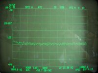
My measurements confirmed this for the most part. For example, with a ZTX849 input transistor, even with an "ordinary" 2N3904 the net noise did not significantly increase. However, a few transistors in the CB position did significantly increase the noise in a way that the noise model does not seem to predict. As an example, I tested some house marked "NSST13029" which were sold as "similar to 2N4401". Two examples are shown below, one (#2) is about 3dB noisier than the other at about 1.3nV/sqrt(Hz) vs about 0.9 nV (#1), at a collector current of 1mA.
#1:
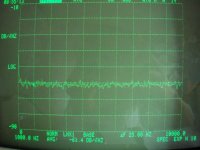
#2:
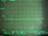
When #2 is the input transistor with #1 as the CB transistor, the noise spectrum is almost the same as #2 by itself:
However, when #1 is the input transistor with #2 as the CB transistor, there is a significant increase in 1/f low frequency noise:
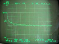
It seems that some transistors in the common base configuration cause significant excess noise. This seems contrary to published models. I guess the models are only that, approximations. For the most part though, if you use a fairly low noise transistor in the common base stage, you are OK.
I made some noise measurements using two transistors in the cascode configuration (common emitter feeding common base). In the cascode you might guess that the noise from the common base transistor does not make a significant contribution, and you would be right, in most cases. In the noise model calculations that I have seen (see for example Motchenbacher and Fichen, "Low-Noise Electronic Design"), the noise voltage contribution of the CB transistor is divided by a large gain term which can be approximated by RL1/re1. I also did some spice simulations which showed that any noise voltage at the base of the CB transistor is typically attenuated by several 1000 times compared to the input signal from the CE transistor stage.
My measurements confirmed this for the most part. For example, with a ZTX849 input transistor, even with an "ordinary" 2N3904 the net noise did not significantly increase. However, a few transistors in the CB position did significantly increase the noise in a way that the noise model does not seem to predict. As an example, I tested some house marked "NSST13029" which were sold as "similar to 2N4401". Two examples are shown below, one (#2) is about 3dB noisier than the other at about 1.3nV/sqrt(Hz) vs about 0.9 nV (#1), at a collector current of 1mA.
#1:

#2:

When #2 is the input transistor with #1 as the CB transistor, the noise spectrum is almost the same as #2 by itself:

However, when #1 is the input transistor with #2 as the CB transistor, there is a significant increase in 1/f low frequency noise:

It seems that some transistors in the common base configuration cause significant excess noise. This seems contrary to published models. I guess the models are only that, approximations. For the most part though, if you use a fairly low noise transistor in the common base stage, you are OK.
I am not sure how to answer your question. The "amplifier" includes the input transistor under test and its gain. The second and third stages are op amps; at first I used a LME49860 but then burned it out so switched to a NE5532, these are not the lowest noise but they don't really have to be because in most cases the gain of the first stage overwhelms any noise from the op amp stages. For example, in my setup the transistor stage gain is about 77 (I vary the load resistance to maintain a constant gain at 1 or 10mA), so if the transistor is say 0.2nv/sqrt(Hz), 77x0.2 is 15.4nv/sqrt(Hz). The noise contribution from the resistors and op amps is significantly less than this. For my measurements I estimate that the "amplifier" adds less than 10% to the measured noise
Similar to the Quan-Tech 5173 Noise Analyzer -- but they use a voltage controlled amplifier such that the net gain of the "Device Under Test" is constant --
The 2N4401/3 were intended for high speed switching, not low noise. The low Rbb helped get charge in and out of the base quickly.....As an example, I tested some house marked "NSST13029" which were sold as "similar to 2N4401". Two examples are shown below, one (#2) is about 3dB noisier than the other at about 1.3nV/sqrt(Hz) vs about 0.9 nV (#1), at a collector current of 1mA....
Long ago some high speed switching transistors used tricks like gold doping to speed switching up. This spoiled current gain and probably caused high noise levels with recombination
It seems that some transistors in the common base configuration cause significant excess noise. This seems contrary to published models. I guess the models are only that, approximations. For the most part though, if you use a fairly low noise transistor in the common base stage, you are OK.
It would be interesting to see the input noise current spectrum of those transistors. In the cascode circuit, their base current noise gets added to the noise coming out of the collector of the common-emitter device, so they must have a huge base current excess noise. I guess davidsrsb's explanation explains why.
- Status
- This old topic is closed. If you want to reopen this topic, contact a moderator using the "Report Post" button.
- Home
- Design & Build
- Parts
- Some transistor voltage noise measurements