I found a nice delaying circuit to switch on the B+ circuit of my PSU. It's just what I need:
http://www.ultranalog.com/schem/hvdelay.pdf
I have 4 circuits I want to switch on, all 5V/2A for the 4 rectifier tubes: http://www.homepages.hetnet.nl/~rjonkers/psu.gif
I'm planning to use 4 of these 12V relays http://www.farnell.com/datasheets/7611.pdf that consume 360mW each
* Now my question, can I switch all 4 relays with just a single 555 circuit, or do I need to build 4 circuits like the one above?
* Is it ok to use 13.7v at the input of the circuit (then I will have 12v for the relay as the 555 drops 1.7v)?
Thanks, Ralph
Hi,
For your questions
1 - No I wouldn't do that, because you source the output to much and the 555 will break.
I should put 4 BC560 in parallel and with higher input ressistor (not much)
2- The 555 has a large range of operating voltages, but I would put some stabillity around this IC.. beceause it could affect the output. some elco's close to the IC power should do this job.
Last.. read the datasheet for timing, when the relays comes up.
Grtz,
Remco Blankesteijn
I don't agree with Mr. Blank.
First of all: You must get the datasheet of the same brand as the one you have. LM555 isn't exactly the same if we talk ON, National etc. certainly not the CMOS type.
If we take National:
16 volt max as supply voltage and absolute max is 18 V.
Max current is 200 mA, your load is 120 mA.
The only thing you have to think about is to add a diode 1N4001-7 across the relay coils, cathode towards +.
Let me also add, it isn't wrong to be a little bit cautious, a separate transistor doesn't hurt.
The IC will be a PHILIPS SEMICONDUCTORS, Manufacturer Part Number NE555N. Maybe I should look for a relay that consumes a little less power.
Ralph said:SNIP
* Now my question, can I switch all 4 relays with just a single 555 circuit, or do I need to build 4 circuits like the one above?
SNIP
Thanks, Ralph
Or you can let one (smal) relay operate the other 4.
Keld
Ralph said:The IC will be a PHILIPS SEMICONDUCTORS, Manufacturer Part Number NE555N. Maybe I should look for a relay that consumes a little less power.
If Philips also can deliver 200 mA I see no reason why you can use a 120 mA load (4 x 0.36/12).
Ralph,
Why so many relays?
Surely you just need 1 x 2-pole relay per monoblock.
It is only necessary to interrupt 1 heater connection on each rectifier🙂
Cheers,
Why so many relays?
Surely you just need 1 x 2-pole relay per monoblock.
It is only necessary to interrupt 1 heater connection on each rectifier🙂
Cheers,
Hi John 😉
I selected two 2-pole relays from Farnell:
959-455 DPCO, 10A - 44.62 Series
http://www.farnell.com/datasheets/4039.pdf
and
431-382 DPCO, 8A - 40.52 Series
http://www.farnell.com/datasheets/396.pdf
both are rated as 55mA consumption (so 110 together, which is way within the 200mA 555 specs). Will they both be ok?
Ralph,
I think the relays willl be OK. But why 2?
Cheers,
PS Don't forget to add a reverse biased diode across the coil.
I think the relays willl be OK. But why 2?
Cheers,
PS Don't forget to add a reverse biased diode across the coil.
Well, the 300B circuit has 2 rectifiers (L+R) and so has the 5687 circuit. That makes 4 high voltage circuits and therefor I need two 2-pole relays.
And I won't forget the diode, it's in the schema I'll build (D1) http://www.ultranalog.com/schem/hvdelay.pdf
And I won't forget the diode, it's in the schema I'll build (D1) http://www.ultranalog.com/schem/hvdelay.pdf
Hi,
Why use a LM555 or a NE555? It is not well suited for a power-up delay. Although it is possible. Attached a circuit I build a long time ago for a LS switch-on delay of a SS amp. I re-dimensioned R1 and C1 for a delay of app. 60 sec. It will be slightly longer I think, somewhere between 70-80 sec. It can be powered from the 12.6V DC heater supply and can easily power 200 mA to one or more relays. Power supply is not critical somewhere between 12V an 15V is ok. D1 is there to quickly discharge C1 when powered down.
Keep the good art of discretes alive 🙂
😎
Attachments
Ralph said:Well, the 300B circuit has 2 rectifiers (L+R) and so has the 5687 circuit. That makes 4 high voltage circuits and therefor I need two 2-pole relays.
And I won't forget the diode, it's in the schema I'll build (D1) http://www.ultranalog.com/schem/hvdelay.pdf
Ah, I was confused as you said 4 relays in your first post

Cheers,

Hi Pjotr, thanks for the schema. Just ordered the parts from Farnell. Will post results. What is the formula for timedelay for this schema?
Hi there,
I'm currently building an amplifier with 2x625VA toriod transformers. (paralleled
To just turn them on with a switch isn't such a good idea, beceause of the inrush current.
I thought in this thread you could use it.
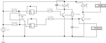
With this schematic it wil reduce the inrush current by switching it first powering it on with a resistor is series, and then another relay takes it over to turn it on full power.
It also reduces the inrush on your secondairies.
In the picture you see the timedelay, the first relay is on when you put a pulse on the D-flip-flop. Later the second will take it over.
When switching it off, I delayed the first relais, the first will go off, and later the second relais(with resistor in series), to prevent sparks on the relais-contacts.
Maybe any hints comments on this?
Grtz,
Remco Blankesteijn
I'm currently building an amplifier with 2x625VA toriod transformers. (paralleled
To just turn them on with a switch isn't such a good idea, beceause of the inrush current.
I thought in this thread you could use it.
With this schematic it wil reduce the inrush current by switching it first powering it on with a resistor is series, and then another relay takes it over to turn it on full power.
It also reduces the inrush on your secondairies.
In the picture you see the timedelay, the first relay is on when you put a pulse on the D-flip-flop. Later the second will take it over.
When switching it off, I delayed the first relais, the first will go off, and later the second relais(with resistor in series), to prevent sparks on the relais-contacts.
Maybe any hints comments on this?
Grtz,
Remco Blankesteijn
Attachments
Remco, this is a good try but I think Pjotrs circuit is more of what you need.
1 Avoid high speed flip-flops! I get chills when I see that. So sensitive against transients.
2 Must use a diode across the relay coil.
3 The reset time must be very short. If you get a short power interuption your circuit must be ready. This circuit is for the inrush current of the transformer itself. Reset time less than 1 second, 300 ms is good.
4 The time is 1-2 seconds. You don't need more.
Hi Ralph,
The time delay is app. 0.5 x R1 x C1. This is not that accurate and it depends slightly on power supply voltage. But it is accurate enough for a power on delay. Do not make R1 larger than 470K. If you need longer times make C1 larger.
After power down it needs some time (app. 15 sec to 30 sec) to recover fully. C1 needs to discharge fully. Otherwise there is a risk that if you switch on the amp again too quickly the circuit will trip the relay on immediately. I have not found this a problem. It is not wise to sequence power of and on too quickly in general.
But if you found this a problem I can hand you a little mod if necessary.
Hi Pjotr,
70-80 seconds will be fine. And in the unlikely event that I switch the amp off and on within 30 seconds, it's no problem that the relay is triggered because the heaters are hot already. At this moment I don't have a delay at all 🙁
I'm planning to use an unused secondary of the powertrafo 0-17V for this purpose. Standard bridge rectifier -> 1000uF -> 40R -> 1000uF -> LM317 set to 12.0v will be the powersupply.
I will use two 2-pole relays of 40mA each to switch on the HT for the 300B and the HT for the 5687 driver (L+R) and I will use one 1-pole relay of 40mA that operates a tricolor LED (15mA) that changes from red at switch-on to green after trigger 🙂 That's 135mA total.
Let you know the results, Ralph
Hi Ralph,
The circuit is not critical and don’t need 1000uF + 40ohm + 1000uF for filtering. That only slows down the release of the relay at power down. If you power it from a 17V winding of the transformer then a single buffer cap of 220uF to 470uF is enough to power 200 mA to the relays. You also don’t need a LM317 for stabilising. A cheap 7812 does the job as well. But if you have a LM317 at hand you can use it as well of course. Oh and don’t forget the caps C4 and C5 close to the stabiliser. These ensure stability of the stabiliser.
Attached the circuit that will do the job. I did not build it but I did simulate it for you and it showed ok. It gave a delay of 70 sec. and it powers down almost immediately. The circuit recovers within 10 sec. R7 is a bleeder resistor to ensure complete discharge of C1 after power down quickly.
Good luck.
By the way, how is your Weller solderstation going?
Peter 😉
Attachments
Hi Peter,
Thanks for this great help, parts will arrive tomorrow and I start building right away. I have a unused LM317 so will use that instead.
Are you THE Peter that helped me choose my soldering station at hifi.nl (the old and good forum) 😉 You see I've come a long way since: http://www.homepages.hetnet.nl/~rjonkers/parts.jpg (the amp I'm building right now)
🙂
- Status
- Not open for further replies.
- Home
- Design & Build
- Parts
- Question about 555 timer circuit with relays