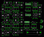
Attached is a layout for a 3 way electronic crossover. Layout is nearly complete with only the power distribution, decoupling caps, and a few signal routes to finish.
My question is would anyone be interested in purchasing these bare boards? They will be 3x4 inches and, if there is enough interest, in the $20 US price range.
Electrical capability per single channel board is -
1 24db LR Low Pass
1 24db LR Band Pass
1 24db LR High Pass
1 Baffle Step Correction
2 Notch Filters
2 Delay Circuits
2 Buffer Circuits
2 Output Level Pots
Baffle Step and Notch filter RC components will be plugable module circuits onto .1 inch headers X1, SL1, and SL2. The IC's are dual 8pin opamps (I plan on using TI OPA2134's).
I unfortunately will not be able to do much on the finalization until mid October, but could probably have boards available in mid November.
Thoughts, feedback, interest?
BobK
Attachments
Here's one ready to buy.
https://secure11.websitecomplete.com/sharrongrp/shop/showProd.asp?prod=1126
https://secure11.websitecomplete.com/sharrongrp/shop/showProd.asp?prod=1126
I know there are a couple of active boards available but I need a three way. Also, to implement an accurate OB design you have to have BS correction, notch filter for most drivers, and phase (delay) compensation. Implementation is much cleaner if you can do this all on one board.
BobK said:I know there are a couple of active boards available but I need a three way. Also, to implement an accurate OB design you have to have BS correction, notch filter for most drivers, and phase (delay) compensation. Implementation is much cleaner if you can do this all on one board.
I would STRONGLY recommend looking at actual capacitor sizes before finalizing layout. Some boards out there specify 0.2 inch (5 mm) spacing between capacitor leads, but available polypropylene parts greater than 0.01 uF will not fit in that space. Using 0.01 uF parts contrains you to resistor values > 100K if you want to cross over around 100 Hz, which some people might not like doing for noise.
I would recommend supporting lead spacings of 5 mm and 10 mm, since that tends to cover the majority of the cases out there, and the occasional 7.5 mm spacing could fairly simply be bent to fit in. Also remember that caps can be fat little bast*rds, too.
Cheers,
Francois.
Sounds like a very complete solution.
Some beginner's questions (for my own understanding) if you don't mind...
The notch, delay, buffer, and output pots would be for the high and band pass circuits?
Could I use this board for a two way speaker and add a subwoofer or woofer later on?
When would you be looking for a commitment?
Any estimates for the cost to populate the board?
regards
Dave
Dave,
The notch circuits can be used to compensate for a peak in a drivers response, or to remove a peak caused by the baffle the driver is mounted on.
The delay circuits are used to compensate the time delay that exists if you mount all of your drivers in the same vertical plane (this is why some passive designs slope the front baffle board). These would be used to delay the tweeter and Mid output so they would be "in phase" at there respective crossover frequencies.
The buffers are used to isolate any filter circuits from following stages. This may be the adjustment pots on the Xover board, or amplifiers you may use that have low input impedences. I will use them between the notch filters and the output level pots.
The pots or trimmers can be used to adjust for efficiency differences between your woofers, mids, and tweeters(only 2). My woofers and mids are more efficient than my tweeter so I will use them to pad the output of the low pass and band pass sections.
You can certainly not use the bandpass section if you are only doing a 2 way. You could reconfigure the board later on to add a woofer.
I would like to order the boards around the end of October. Cost will vary depending on the quality of parts you use. I plan on using OPA2134's but any other dual opamp with the same functionality could be used.
Rough cost -
8 - Opamps @ 2.63
27 - 1% metal film resistors @.20
16 - polyprop caps @ .70
2 trimmers, bypass caps,input cap, headers ~ $11
Power supply ~$20
Rough estimate to do a stereo pair without case would be around
$160.
Hope this helps
Jens,
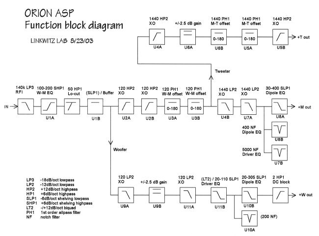
I don't have a schematic of the board but all of the circuits are from the attached Linkwitz site.
http://web.archive.org/web/20030605092830/linkwitzlab.com/filters.htm
I wanted to do a board that would support a varied DIY and prototype environment. The most flexibility would be offered by a board with the above circuits that could be configured by jumpers or point to point wiring between the various functional blocks.
I've admired the projects you have shared with this community and look forward to any suggestions you may have.
I'm building a three way crossover on stripboard at the moment, with a view to creating a PCB later. To have the opportunity of a ready built PCB, with the same configuration that I am building, is an opportunity too good to miss. So count me in.
Dunno how much shipping to the uk would add to the cost though, maybe someone with experience in that could help.
Dunno how much shipping to the uk would add to the cost though, maybe someone with experience in that could help.
Well, with all the stuff you're putting in 3x4 inches is ambitious. You might want to look at a larger board for all that stuff, especially with participants (CarlosFM in particular) on other forums talking up heavy bypassing on every single opamp, as well as biasing opamps into class-A with resistors between output and V-.
I also think you really want to reexamine how *wide* polypro caps tend to be, and how difficult it is to get 2x values of components. Many people use two caps in parallel to make up the 2C parts of Sallen-Key filters. All that's gonna make your boards bigger, I'm afraid.
Another note: I find it's easier to tune a system with respect to the mids rather than the highs. I prefer trimmers on the high and low bands, with +10dB gain before the trimmers, but NOT the midband. A 10 turn linear trimmer means the entire last turn covers -19 dB to -infinity dB (9R:1R on down), and the gain configuration above means the trimpot will be in the middle of the range for equal sensitivity drivers. You don't even pay a noise penalty since the gain comes in before the trimmers, and any approach to clipping is academic since your amplifiers would clip before your trimpot drivers anyway, especially if the output buffers have more than unity gain (I recommend 2)
Cheers,
Francois.
BobK said:Rough cost -
8 - Opamps @ 2.63
27 - 1% metal film resistors @.20
16 - polyprop caps @ .70
2 trimmers, bypass caps,input cap, headers ~ $11
Power supply ~$20
Rough estimate to do a stereo pair without case would be around
$160.
You could probably just buy John PoMann's Active XO exploration kit for $85 and have all the above + parts left over
http://www.snippets.org/filters/crossover.htm
dave
BobK said:I don't have a schematic of the board but all of the circuits are from the attached Linkwitz site.
http://web.archive.org/web/20030605092830/linkwitzlab.com/filters.htm
Just a FWIW, SL recently switched to a host ISP that can handle his bandwidth so you can access his all pages directly once again. The filter page is at:
http://www.linkwitzlab.com/filters.htm
catapult said:
Just a FWIW, SL recently switched to a host ISP that can handle his bandwidth so you can access his all pages directly once again. The filter page is at:
http://www.linkwitzlab.com/filters.htm
And his Phoenix crossover board is great! I'd buy it today if I didn't need things like 24 dB/oct low->mid & some other tweakiness.
Francois.
SL upgraded the Phoenix board so you can put everything for a channel of the Orion on one board. It's pretty versatile but it's $50 which is more expensive than Bob's proposed board. It's also bigger at 7"x8", whatever that means.
http://www.linkwitzlab.com/pcb.htm
http://www.linkwitzlab.com/pcb.htm
The Linkwitz boards are excellent. Anyone who can complete their project with the functionality they provide please purchase his units. He has been the pioneer in open baffle design and provided invaluable insight into active filter correction of speaker response. We in the DIY community owe him our support. Please support him if possible.
His boards can be purchased at:
http://www.linkwitzlab.com/pcb.htm#ASP printed circuit
His boards can be purchased at:
http://www.linkwitzlab.com/pcb.htm#ASP printed circuit
catapult said:SL upgraded the Phoenix board so you can put everything for a channel of the Orion on one board. It's pretty versatile but it's $50 which is more expensive than Bob's proposed board. It's also bigger at 7"x8", whatever that means.
http://www.linkwitzlab.com/pcb.htm
Dude, you RULE. That's 95% of what I'm looking for, and the tweeter Linkwitz transform I can kluge trivially on some perfboard. Thanks for the tip!
Francois.
DougL said:I may be reading the schematics wrong but I think U6B and U5A
are a transform for the tweeter.
HTH
Doug
No, that's the delay so the highs are time-aligned with the mids. PH1 is a first-order allpass, and he cascaded two of them so the delay is linear until an octave above the crossover frequency.
Thanks anyway,
Francois.
- Status
- This old topic is closed. If you want to reopen this topic, contact a moderator using the "Report Post" button.
- Home
- Loudspeakers
- Multi-Way
- Electronic Crossover PWB