Hoping for some input on a passive cross-over box design that will allow me to mount various mid-high frequency concepts on top of a wide-range bass unit. This lets me build a variety of smaller experimental units without continually rebuilding the bass unit.
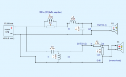
As shown in the overall system design, the proposal would be modify a simple 2nd order High/Low cross-over model with variable length inductor arrays. The amount of inductance on each could be changed together using something like a "KCT 2 Pole 6 Position Dual Decks" rotary switch ($8).
In X-Sim it can be shown that choosing a 20uF capacitor on each side, varying inductance from 1mH to 10mH changes the cross-over frequency from 300hz to 1.1khz.
10 mH - 300 hz
7.5 mH - 400 hz
5 mH - 500 hz
3 mH - 600 hz
2 mH - 850 hz
1 mH - 1.1 khz
An optimal solution would be 6 separate cross-overs, each with their own capacitance value. Help me understand why that's worth the effort?
This design could be built using 2 x 20uF capacitors, 3 x 1mH, 1 x 2 mH, and 2 x 2.5mH inductors, wired in series to the next inductor and the switch, on each side (8 passives) along with whatever BSC filter you need on the front-end.
Looking for critical feedback and improvement ideas. Thanks in advance!
Attachments

I would go active line level, much easier. Changing crossover fr can be done by single pot or switching some capacitors.
Or mini dsp, by software.
Or mini dsp, by software.
Yes, I have a nice Dayton DSP unit. You can change profiles from your cell phone. But being able to drop a bookshelf speaker (Heil AMT, open baffle mid/high, etc.) on top of my bass unit, turn the dial and go... has its appeal... as well.
I am not familiar with dayton dsp.
Minidsp is crossover, you can change crossover frequency, slope, phase, delay...all on while you listen. Dial and go.
But if you want to spend fortune on coils, suit yourself.
Minidsp is crossover, you can change crossover frequency, slope, phase, delay...all on while you listen. Dial and go.
But if you want to spend fortune on coils, suit yourself.
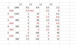
This formula gives steeper slopes:
L3 C1 L2 C2
1 1300 0.5 6.8 0.5 2.2
Add 0.5 new 0.5 4
2 1100 1 20 1 6.2
Add 0 60 1.5 6.8
3 800 1 80 2.5 12.5
Add 0 20 0 6.8
4 500 1 100 2.5 20
Add 4 0 2.5 20
5 300 5 100 5 40
Add 2.5 20 0 13
6 200 7.5 120 5 53
L3 C1 L2 C2
1 1300 0.5 6.8 0.5 2.2
Add 0.5 new 0.5 4
2 1100 1 20 1 6.2
Add 0 60 1.5 6.8
3 800 1 80 2.5 12.5
Add 0 20 0 6.8
4 500 1 100 2.5 20
Add 4 0 2.5 20
5 300 5 100 5 40
Add 2.5 20 0 13
6 200 7.5 120 5 53
Attachments
The low-pass filter in XSim produces very different curves when capacitors and inductors are laddered together vs. atomic. In both paths, inductance is 7.5mH and capacitance is 120 uF. Yellow is atomic (1 pcs each passive component), red is the laddered one (would have switches between).
Attachments
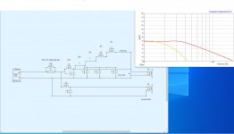
This shouldn't be a surprise. One is a 2nd order network, the other is a 3rd order.
The main problem with your approach is the fact that 2 coils in series work like a single coil with a summed inductance only if the two coils are well spaced apart. If not there is a sensible cross talk effect.
Another problem is that in order to change crossover frequency and maintain a predefined kind of slope (for example LR2), you have to change both the coil and the cap.
Ralf
I makes very little sense to build a baffle step correction circuit and then to also add a LP filter. An appropriate coil will correct for baffle step and provide the desired LP filter.
Ralf,
Thanks for helping me and others like me in the future to understand the challenges with this approach.
And yes, resistor across the coil array is an effective baffle step.
Thanks so much.
Thanks for helping me and others like me in the future to understand the challenges with this approach.
And yes, resistor across the coil array is an effective baffle step.
Thanks so much.
It makes very little sense to build a baffle step correction circuit and then to also add a LP filter. An appropriate coil will correct for baffle step and provide the desired LP filter.
Yes!
Just the opinion I was seeking.
Would it be only a single series inductor(with maybe a zobel across the driver) to accomplish both
LOW PASS and BSC, or would the single inductor have a parallel resistor (and if so, how would the parallel resistor affect the slope of the low pass filter)?
Much obliged,
-Charles
Do you input actual impedance measurements of the speakers to use this? If not, do you understand that the messy impedance of actual satellite speakers means the passive highpass only works very crudely? I cannot tell. (There IS a sim package where someone was doing this and it worked OK but sorry I don't remember that thread).X-Sim
- Add me to the "do it in DSP, life will be better" crowd.
Yes, I will be using the (Zobel-stabilized) impedance of the speakers I plan to use at least 2 octaves from any peaks or resonances.Do you input actual impedance measurements of the speakers to use this?
So will you please answer my query?
Thanks. 🙂
If you mean "Help me understand why that's worth the effort?" well I don't think it is, seems like a lot of work to end up with some nonideal crossovers if you simplify as you said. Because you also need some significant parts to do good Zobels, don't you?!? And those impedances are all at static measurement-when the woofer is actually moving those impedances dance around a tiny bit. Maybe not significant but...anyway as I said before I'd just do it active. Then you can adjust different frequencies easily, instead of "oops neither of these passive settings is quite right."So will you please answer my query?

Many people have the false idea that going active is always easier. What is easier is the capability to quickly change crossover point, slopes, delay. What is NOT different to a passive approach is the fact that you need to measure, and this is IMHO the hardest part of a DIY project.
For a passive approach you need to measure both FR and impedance, and you input those into a crossover simulator. A single first coil can act as a first pole of a crossover slope and baffle step compensation, but you usually accomplish the whole task with (at least) a 2nd order electrical network. Zobels are mainly unnecessary. For an example look here: http://zaphaudio.com/ZRT.html (and be sure to have a look at the transfer functions of the crossover)
Ralf
- Home
- Loudspeakers
- Multi-Way
- Passive / bass unit / variable cross-over