Hello everyone!
I'm currently working on building some Synergy-style horns, which I'll eventually document in another thread. The mid/woofer injection ports appear to be the greyest area when it comes to the design as far as I can tell.
The two main questions I wanted to see if there was a consensus on are:
Here's an attached drawing of part of the design. It's a two-way design, using 4 woofers (6.5" Parts Express Poly Cone) per side, with a FaitalPro 3FE25 at the throat. Feel free to copy the drawing and scribble your thoughts onto it!
Note:
Many thanks!
I'm currently working on building some Synergy-style horns, which I'll eventually document in another thread. The mid/woofer injection ports appear to be the greyest area when it comes to the design as far as I can tell.
The two main questions I wanted to see if there was a consensus on are:
- What is the area of the port in relation to the driver? Or is it not specifically determined by that, and the cutoff frequency has more of a bearing?
- With a Synergy horn, it appears that it's best to tuck the entry ports into the corners of the horn (if using a square/rectangular shape). I've seen circular, rectangular (slit), tear-drop and kidney bean-shaped ports. Which works best?
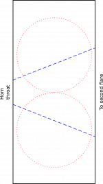
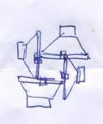
Here's an attached drawing of part of the design. It's a two-way design, using 4 woofers (6.5" Parts Express Poly Cone) per side, with a FaitalPro 3FE25 at the throat. Feel free to copy the drawing and scribble your thoughts onto it!
Note:
- Blue depicts the primary flare of the horn
- Red is the woofer placement
- The black rectangle is a representation of the side panel (not exact, just for display clarity)
Many thanks!
Attachments
Last edited:
The area of the multiple entry horn (MEH) mid or woofer port should be large enough to allow the displacement of the driver to cause minimal air turbulence noise, so larger drivers require larger ports area.
Too large, and the open area may cause HF diffraction and reflection problems, erratic frequency response that varies off axis, not correctable with EQ/DSP.
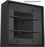
Looking at the port area of the two-way MEH Electro-Voice MTS 4153-64 using four 15” drivers, or any of DSL’s MEH horns, one can see the port area can be relatively small compared to the driver diameter, and still not create turbulence problems.
Ideally, for constant directivity, the MEH ports should be placed within 1/4 wavelength at the crossover frequency, which for crossovers in the 1kHz+ range on 50+ degree horns requires them to be placed as close as physically possible to the HF driver entrance.
In such an arrangement, “tear-drop” or “sausage” shaped ports in the horn corners have less detrimental effect than a round hole of similar area in the center of the horn wall near the throat.
You have chosen a 3” cone driver for HF, presumably so a crossover point in the 500Hz (or lower) range can be used. The LF port position can be optimized for frequency response, which may place it further from the throat, making port placement and shape less critical, as the ports occupy far less area relative to the horn wall area when placed further from the throat.
Centering the port to the cone will make it’s pressure forces more symmetrical, which may sound “cleaner” at high excursion, due to less rocking motion. Putting one cone on each side of the horn, “pinwheel” fashion would allow near center cone port placement while still putting the port entrances near the corners of the horn.
Too large, and the open area may cause HF diffraction and reflection problems, erratic frequency response that varies off axis, not correctable with EQ/DSP.
Looking at the port area of the two-way MEH Electro-Voice MTS 4153-64 using four 15” drivers, or any of DSL’s MEH horns, one can see the port area can be relatively small compared to the driver diameter, and still not create turbulence problems.
Ideally, for constant directivity, the MEH ports should be placed within 1/4 wavelength at the crossover frequency, which for crossovers in the 1kHz+ range on 50+ degree horns requires them to be placed as close as physically possible to the HF driver entrance.
In such an arrangement, “tear-drop” or “sausage” shaped ports in the horn corners have less detrimental effect than a round hole of similar area in the center of the horn wall near the throat.
You have chosen a 3” cone driver for HF, presumably so a crossover point in the 500Hz (or lower) range can be used. The LF port position can be optimized for frequency response, which may place it further from the throat, making port placement and shape less critical, as the ports occupy far less area relative to the horn wall area when placed further from the throat.
Centering the port to the cone will make it’s pressure forces more symmetrical, which may sound “cleaner” at high excursion, due to less rocking motion. Putting one cone on each side of the horn, “pinwheel” fashion would allow near center cone port placement while still putting the port entrances near the corners of the horn.
Attachments


Thanks for the in-depth answer, Art! I've decided to go with the 'sausage' style of ports, as they should be relatively easy to cut out with a drill and a jigsaw. Given that they appear in a lot of really good (commercial and non-commercial alike) designs is evidence enough!
I've also re-worked my plans based on your recommendation of the 'pinwheel' layout. It leads to a slightly larger horn, but it's worth it! Thanks again 🙂
I've also re-worked my plans based on your recommendation of the 'pinwheel' layout. It leads to a slightly larger horn, but it's worth it! Thanks again 🙂