I have been playing around with dipole CBTs and they are pretty cool. My first iteration was a full range version, it worked pretty good but I want to try to do better so here I am with a multiway CBT =)
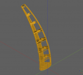
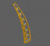
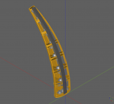
It is a 70 degree 144 cm radius arc. My "woofers" are the same drivers as in the full range version (SB65WBAC) and my midtweeters are GRS 8" Slim.
Instead of doing a line to the left or right of the midtweeters I want to have symmetrical left / right response so my idea is to place the woofers at the cutoffs of the planars. And then have the woofers in a log array such that I don't have to use a shading network.
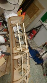
I also want the speaker to look good so I want it to be curved in most directions. This turned out to be pretty hard to do so I set out to learn me some CAD and got some progress playing around with CadQuery.
In the CAD images I have not rendered the rear of the woofer slots, they will be enclosed such that all sound has to go to the front.
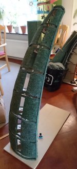
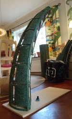
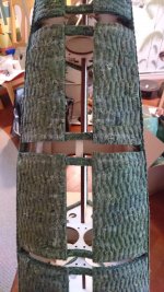
The green-ish image 7 is where I will place sheets of wool carpet as a baffle.
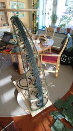
I just got the pieces from the my laser cutting service so could try the fit, so far it looks pretty good. If all goes well I'll probably be able to start measuring next weekend.
It is a 70 degree 144 cm radius arc. My "woofers" are the same drivers as in the full range version (SB65WBAC) and my midtweeters are GRS 8" Slim.
Instead of doing a line to the left or right of the midtweeters I want to have symmetrical left / right response so my idea is to place the woofers at the cutoffs of the planars. And then have the woofers in a log array such that I don't have to use a shading network.
I also want the speaker to look good so I want it to be curved in most directions. This turned out to be pretty hard to do so I set out to learn me some CAD and got some progress playing around with CadQuery.
In the CAD images I have not rendered the rear of the woofer slots, they will be enclosed such that all sound has to go to the front.
The green-ish image 7 is where I will place sheets of wool carpet as a baffle.
I just got the pieces from the my laser cutting service so could try the fit, so far it looks pretty good. If all goes well I'll probably be able to start measuring next weekend.
Attachments


Last edited by a moderator:
Cool!
It will be interesting to see how the little fullrange drivers measure under this condition.
It will be interesting to see how the little fullrange drivers measure under this condition.
It will of course be a 3-way with a normal dipole sub. Crossover somewhere in the 140 - 160 hz range @ LR4. The midtweeter crossover will probably be 600 - 1000 hz @ LR4. When I can measure it I'll find out how low I can without getting significant distortion.
Last edited:
What a fresh way to do it, very nice!
It sure looks more balanced this way, with the tapering towards the top.
Should be interesting to see how it measures.
It sure looks more balanced this way, with the tapering towards the top.
Should be interesting to see how it measures.
More progress!
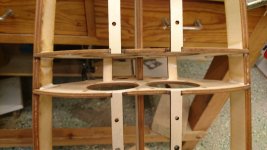
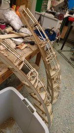
Most of the plywood frame is now done and glued. The missing bit is closing up the woofer slots. I didn't order laser cut pieces for that partly because I wanted to save money and partly because the parts are angled in most directions so I'd have to post process them anyway.
In the images only the top slot has had slot walls added.
The priority as of now is:
1. Close up all the woofer slots.
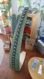
2. Glue wool felt sheets as baffles and along the edge of the speaker.
3. Build a preliminary base.
4. Test mount the drivers, do some temporary wiring and then measure it!
I hope to get 1. done by tomorrow but 2-4 will have to wait until next weekend.
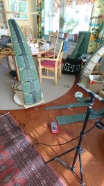
And in case anyone wonders the main reason for having it tapered is because I think it looks really nice. It reduces the visual pollution a lot when the eye level width is fairly small.
Most of the plywood frame is now done and glued. The missing bit is closing up the woofer slots. I didn't order laser cut pieces for that partly because I wanted to save money and partly because the parts are angled in most directions so I'd have to post process them anyway.
In the images only the top slot has had slot walls added.
The priority as of now is:
1. Close up all the woofer slots.
2. Glue wool felt sheets as baffles and along the edge of the speaker.
3. Build a preliminary base.
4. Test mount the drivers, do some temporary wiring and then measure it!
I hope to get 1. done by tomorrow but 2-4 will have to wait until next weekend.
And in case anyone wonders the main reason for having it tapered is because I think it looks really nice. It reduces the visual pollution a lot when the eye level width is fairly small.
Attachments

More progress! No measurements yet but I hope to get some done tomorrow. Unless I've forgotten something then the only thing left is to try and mount all the drivers and then connect them in the appropriate shading network.
Attachments

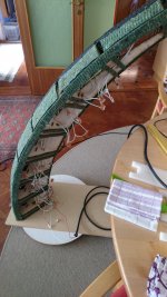
Thinking I'd have measurements done today was perhaps a bit naive. I have massively underestimated how long it will take to mount all the drivers and connect them. At least I have something to look forward to for next weekend =)
-yes, getting the wire correct is tedious.
Remember to get the measurements for wire length correct (..I screwed that up several times with one of my array projects). For me then it was 1st making sure I had the correct size push-tab connectors, measuring and then cutting (hopefully the correct length) and stripping the wire, *crimping the connectors (..and then hot-gluing the connections). The actual time connecting wasn't to bad though.
*repetitive stress injury.
Last edited:
At last! Results!
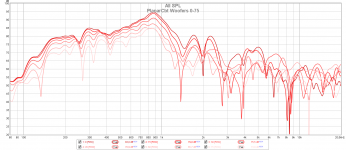
The woofers performed beautifully. No sharp peaks and very consistent response, would be very easy to cross 600-800 hz @ LR4.
The planars, however, doesn't perform as well. Not nearly as smooth and consistent response. As I've measured my prototype which only uses the SB65 full rangers performs more consistent and smooth in the high frequencies.
I ripped away the wool baffles from the planars to see if it improved the response but no, problem still remains.
I have looked for errors like for example if the shading network is connected wrong but it looks and measures correct. The planars might perform better in a straight array without shading but I want to build a shaded CBT. Unless I can improve response I'll probably sell the planars and go back to only using the full rangers.
Attachments
-
 DSC_0734.jpg537.2 KB · Views: 178
 -
 DSC_0735.jpg522 KB · Views: 167
 -
 DSC_0736.jpg435.2 KB · Views: 170
 -
 PlanarCbt Woofers 0-75.png154.6 KB · Views: 182
 -
 PlanarCbt Planars 0-75 1x1m.png140.1 KB · Views: 179
 -
 PlanarCbt Planars naked 0-75 1x1m.png140.5 KB · Views: 130
 -
 DSC_0738.jpg596.5 KB · Views: 135
Points for your enthusiasm and efforts to try and combine the shape of a physically curved CBT and a dipole. But I think you should step back and do some thinking about what is going on with this setup before continuing. Here's why:
The CBT is meant to simulate a section (a slice) of a spherical cap, the spherical cap being a portion of a hypothetical sphere, the sphere being an equidistant surface from a central point source. Acoustic radiation is assumed to originate from the central point lying at the center of the sphere from which the cap is taken. The CBT's delay and shading is meant to better approximate this geometry from a series of identical drivers placed along a curve. All the drivers in Keele's CBT are in closed boxes for this reason as well.
When you try to reinvent the CBT as a dipole, you end up destroying much of the acoustic geometry upon which the CBT is basede. Even though your array is curved, the rearward radiation is not "inward falling" to a point (as would the CBT "in reverse"). Instead it is simply a curved and displaced line source that radiates outwards to the rear. That is quite different from what is going on with the CBT and there is really nothing that you can do to change that - it's built into your curved dipole line. Therefore, you cannot produce a kind of "dipole cousin" of the CBT using this approach.
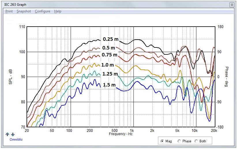
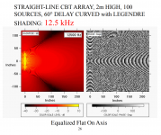
There is a reason that the width of the CBT section is quite narrow, and that is because wider baffles cause interference at lower frequencies, the wider the baffle the lower the band where the interference occurs. Even in the CBT this is happening above 5kHz or so, as seen in this plot:
If you wish to create a dipole array a narrow vertical array with the drivers arranged physically in a line, straight up and down would be a much better physical arrangement. It would be amenable to shading and delaying of the line to reduce interference. You would still not really obtain the CBT radiation pattern. It would be a shaded dipole line array, and that would very likely be quite enjoyable.
The CBT is meant to simulate a section (a slice) of a spherical cap, the spherical cap being a portion of a hypothetical sphere, the sphere being an equidistant surface from a central point source. Acoustic radiation is assumed to originate from the central point lying at the center of the sphere from which the cap is taken. The CBT's delay and shading is meant to better approximate this geometry from a series of identical drivers placed along a curve. All the drivers in Keele's CBT are in closed boxes for this reason as well.
When you try to reinvent the CBT as a dipole, you end up destroying much of the acoustic geometry upon which the CBT is basede. Even though your array is curved, the rearward radiation is not "inward falling" to a point (as would the CBT "in reverse"). Instead it is simply a curved and displaced line source that radiates outwards to the rear. That is quite different from what is going on with the CBT and there is really nothing that you can do to change that - it's built into your curved dipole line. Therefore, you cannot produce a kind of "dipole cousin" of the CBT using this approach.
There is a reason that the width of the CBT section is quite narrow, and that is because wider baffles cause interference at lower frequencies, the wider the baffle the lower the band where the interference occurs. Even in the CBT this is happening above 5kHz or so, as seen in this plot:
If you wish to create a dipole array a narrow vertical array with the drivers arranged physically in a line, straight up and down would be a much better physical arrangement. It would be amenable to shading and delaying of the line to reduce interference. You would still not really obtain the CBT radiation pattern. It would be a shaded dipole line array, and that would very likely be quite enjoyable.
Try filling-up the fullrange driver slots with the same absorptive material - my guess this is where much of the irregularity is coming from.
When you try to reinvent the CBT as a dipole, you end up destroying much of the acoustic geometry upon which the CBT is based. Even though your array is curved, the rearward radiation is not "inward falling" to a point (as would the CBT "in reverse"). Instead it is simply a curved and displaced line source that radiates outwards to the rear. That is quite different from what is going on with the CBT and there is really nothing that you can do to change that - it's built into your curved dipole line. Therefore, you cannot produce a kind of "dipole cousin" of the CBT using this approach.
Hi Charlie,
Don Keele wrote a paper on dipole CBTs here. https://faculty.tru.ca/rtaylor/publications/cbt_dipole.pdf
He implemented the design here.
https://faculty.tru.ca/rtaylor/publications/dipole_cbt_implementation.pdf
You can make a straight dipole CBT by delaying+shading each bank. One advantage of a straight array is you can easily adjust the vertical beamwidth, you aren't stuck with one half angle. I think you should try building one because I think you'd like it.
Wow, I did not know that, but I don't keep up with the literature. Thanks for posting the link to the technical paper and the prototype. I will give them a read.
I remain a bit skeptical for the reason I mentioned before: each driver is essentially radiating into "less space" to the rear than to the front and I think that would distort the combined output and the dipole pattern, etc. But perhaps that is just not a serious problem. It will be somewhat dependent on the radius of curvature, and would be worse as the arc radius decreases and arc length increases. Also, the prototype described in the paper is only 3" in width (!) and wider arc-baffles will have a limited range of usefullness as a dipole because the dipole peak will occur lower in frequency and above that the pattern will be a bit messy. Again, hard to say how this would work out for a line array, so I hope to see a more detailed loudspeaker build using these principles from Keele to flesh out the concept.
I still think it would be much better (or at least easier) to construct a vertical dipole array with shading/delay.
Last edited:
Yes, those papers are what got me to start toying with dipole CBTs.
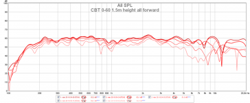
And I know it works. I have build a prototype of a dipole cbt with full range drivers (same drivers I used as woofers in this speaker) and while not perfect it performs pretty good. More importantly I use this as my baseline since the planar version has to perform significantly better than this one to be worth it. Doesn't look like it though when considering overall smoothness. The full range CBT in the shown measurement uses no EQ except a 3rd order highpass @ 160 hz.
But I'm thinking you might be right Charlie in that the planar drivers will probably perform better in a straight array without any physical or digital delay.
And while I could test the planars in a straight array I'm not convinced it is the ideal speaker for me. The CBT design measures amazinly consistent inside the room when I walk around. I also only have enough drivers for a 1.6m tall array so the response consistency would start to deteriorate. The shaded CBT is nice here because it doesn't need to be that tall to measure consistent. It also doesn't visually pollute the room as much which is nice.
Edit: I'm toying with the idea of sealing the rear of every second or third driver driver in the full range array to get a cardioid or supercardioid response. Afraid I'll loose the dipole magic though so I haven't tried it yet. Also a dipole array meshes very well with the dipole sub where a cardioid or supercardioid wouldn't be as good.
Attachments
Last edited:
Try filling-up the fullrange driver slots with the same absorptive material - my guess this is where much of the irregularity is coming from.
Might also check on what's happening as far as the reflection off of the support spline in the rear.
No I meant you (OllBoll) SHOULD still use electronic delay and shading if the line is a straight one. Without those to tailor the wavefront, there will be a lot of comb filtering just like with a long (but not "infinite") line array.
The advantage of the straight line is that, if you can really get the drivers to operate as a dipole within their bandpass(es), then you essentially have the mirror image of what is happening to the front of the array happening to the rear.
My guess is that Keele has as his intended audience/application a large performance space, where you need to illuminate the audience uniformly with an array. In that case, the radius of curvature of the physically curved dipole array would be very large, and thus the rear side "space constraint" would be a non-issue. This isn't quite the same as when the loudspeaker is in your living room and the radius of curvature is only a few feet.
Anyway, if you like the project go for it! It is certainly interesting and a new type of dipole system.
No I meant you (OllBoll) SHOULD still use electronic delay and shading if the line is a straight one. Without those to tailor the wavefront, there will be a lot of comb filtering just like with a long (but not "infinite") line array.
The advantage of the straight line is that, if you can really get the drivers to operate as a dipole within their bandpass(es), then you essentially have the mirror image of what is happening to the front of the array happening to the rear.
Sure, the front-back response would be mirrored along the middle of the line where now the mirror response is reflected down but I don't see how it would improve the response apart from that. If anything, I think it would perform worse since the planars are 20 cm high and since they are physically curved then they have a different delay at the bottom from the top. With a digital delay each driver this would not be possible since I would have to have a flat delay for the whole driver. Wouldn't that create more interference problems?
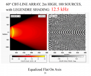
If we look at Line Array Sound-Field Comparison - 5. STRAIGHT-LINE ARRAY (Delay Curved With Shade) from the goodie cd. The simulation is a CBT of 100 sources with 20mm CTC distance. The delay version falls apart at 12.5 khz. With a 200mm CTC with the planars and a flat delay for the whole area of each driver, won't this issue creep down a lot in frequency, possibly down to 1.25 khz?
Attachments

To me, a good dipole speaker has similar radiation pattern and response tonality at 0 and 180 deg, and preferably also mirrored off-axis. When this kind of speaker (pair) is put on the long wall of the room, we get the dipole magic - you're in a good concert hall.
I'm wondering how this CBT dipole will radiate on backside, we will see.... I have lots of doubts concerning horizontal and vertical radiation patterns and thus how the reflected sound will be in a typical domestic listening space. Dr. Keele's and all other CBT studies published show only frontside dispersion (quasi-anechoic or in-room)
I'm wondering how this CBT dipole will radiate on backside, we will see.... I have lots of doubts concerning horizontal and vertical radiation patterns and thus how the reflected sound will be in a typical domestic listening space. Dr. Keele's and all other CBT studies published show only frontside dispersion (quasi-anechoic or in-room)
- Home
- Loudspeakers
- Multi-Way
- Groundplane Dipole CBT