hi,
try to build crossover for jbl 2445j 16 ohm compression driver.
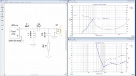
first, i build it with Xsim software, i design 22uf and 4mH.
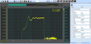
then i connect the part to amplifier and measure the results with 16 ohm resistor load.
the results are fine, 12db/dec, 650hz -3db point.
but when i replace the resistor with the driver, the slope change.
i replace caps, amps, coil. nothing help to solve it
try to build crossover for jbl 2445j 16 ohm compression driver.
first, i build it with Xsim software, i design 22uf and 4mH.
then i connect the part to amplifier and measure the results with 16 ohm resistor load.
the results are fine, 12db/dec, 650hz -3db point.
but when i replace the resistor with the driver, the slope change.
i replace caps, amps, coil. nothing help to solve it
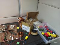
Attachments
Last edited:
Dome tweeters with ferrofluid (for example) have a very flat impedance curve, so the crossover works as intended.
For a test, you could put an 8ohm resistor across the compression driver. I would expect the transfer function to work pretty much as intended, albeit with power loss in the resistor.
The next step is an LCR impedance flattener (or two) across the driver.
Chris
For a test, you could put an 8ohm resistor across the compression driver. I would expect the transfer function to work pretty much as intended, albeit with power loss in the resistor.
The next step is an LCR impedance flattener (or two) across the driver.
Chris
hi,
try to build crossover for jbl 2445j 16 ohm compression driver.
first, i build it with Xsim software, i design 22uf and 4mH.
then i connect the part to amplifier and measure the results with 16 ohm resistor load.
the results are fine, 12db/dec, 650hz -3db point.
but when i replace the resistor with the driver, the slope change.
i replace caps, amps, coil. nothing help to solve it
At the risk of being pedantic, I'd suggest being careful about using the term "crossover distortion" here, since the term "crossover distortion" does have a pretty specific meaning related to amplifier design (and is unrelated to the loudspeaker crossover).
Crossover distortion - Wikipedia
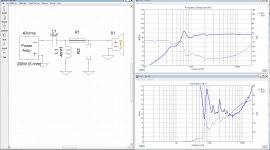
If I interpret your pictures correctly, sim and measurement now match. Next step is optimizing the LC values. Unfortunately in XSim trial and error are the only way. Toggle the values until you see red in the face. A network consisting of one L and one C is probably too simple, so you may end op added further components.
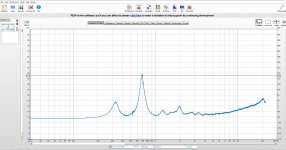
The reason that you have such a peaked impedance is because of the horn. A better horn would not have such a rough impedance and you would get a better result. You could also, as mentioned before, put a resistor across the CD, thus flattening the impedance, but the resonances from the horn will still be evident in the output SPL.
no speaker has a constant impedance load at all frequencies. you can't use a dummy load as the speaker itself. measure the impedance of the driver or simply digitalize the impedance curve in the datasheet or use Vituixcad graph tracer (it's the best I've used). then import the impedance into Xsim for an accurate simulation.

Hi,
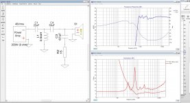
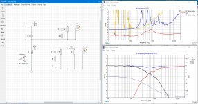
I would like to hear your opinion on the following design: (2-Way)
I connected the crossover in a series, because the impedance dropped to 2 ohm on the horn.
The impedance dropped to 2 ohm because that's what lowered the peaks (blue line). strange, no cap in the zobel network.
Is the design correct?
Many thanks
Attachments
Last edited:
- Status
- This old topic is closed. If you want to reopen this topic, contact a moderator using the "Report Post" button.
- Home
- Loudspeakers
- Multi-Way
- compression driver causes crossover distortion