This is a project based around the B-52 PHRN-1014 1" Horn 10" x 14" Bolt-On waveguide Inspired by Patrick Batemans excellent results with it:
Mazama
https://www.diyaudio.com/forums/multi-way/350889-improved-lens-3.html#post6122375
The idea is to make a super compact and powerful PA speaker by turning this wave guide into two way unity horn and adding side mounted woofers. Preliminary crossover points and drivers are:
1500 Hz - 20kHz: Eminence N151M-8
300 Hz - 1500Hz: 4*B&C 4NDF34 this driver seems exceptional for unity/MEH horns:
https://www.diyaudio.com/forums/mul...-bandpass-mid-unity-horn-240.html#post6414665
I recall from my previous MEH project that motor strength seemed to be the limiting factor in the high frequency crossover point I had to choose (1.27kHz) so hopefully this will cross higher.
80 - 300Hz: 2*B&C 10CL51 this driver seems to offer a lot of output for its size and weight at a good price so seemed like a decent enough starting point:
Backpack challenge
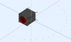
To get an idea of what frequency the side mounted woofers will be usable to I did a BEM sim in AKABAK3.
So from these results we see that the two opposed woofers narrow the beam width to 90 degrees at ~ 275Hz (need to work out how to plot beamwidth).
Lots of sims to work out if this is all possible!
Attachments

Last edited:
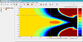
I increased the number of frequency points and changed the graph scaling to get a better idea of the 90 degree horizontal dispersion point. Looks to be 239Hz. I think this will be OK for crossing to the 4NDF34 from this post:
https://www.diyaudio.com/forums/mul...-bandpass-mid-unity-horn-240.html#post6416806
but need to work out the shape of the B52 horn to try and do my own sim.

https://www.diyaudio.com/forums/mul...-bandpass-mid-unity-horn-240.html#post6416806
but need to work out the shape of the B52 horn to try and do my own sim.
Attachments
Nice, great to see these AKABAK simulations!
36cm width of the box would be about wavelength of 953Hz divided by 4 is 238Hz.
36cm width of the box would be about wavelength of 953Hz divided by 4 is 238Hz.
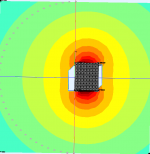
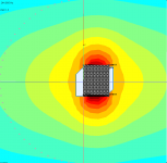
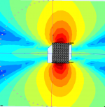
would seem the rules of thumb kind of hold then, although my expectations at 1/4 wl spacing it would still be acting as a monopole source. I attach some SPL plots with frequency that shows how the sound field varies.
100Hz:

244Hz (around crossover):

1057Hz:

100Hz:
244Hz (around crossover):
1057Hz:
Attachments
Interesting idea. A very compact box indeed. Would all the speakers fit inside? And with sufficient volume for the 10" speakers?
This is a good question! I haven't had much time to work on this project and have also changed a number of things I would like to do in this project:
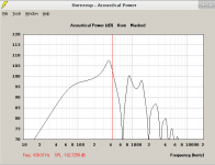
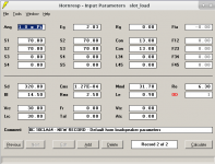
1) change the side mounted woofers to slot loaded side mounted woofers. A quick and dirty Hornresp sim indicates that they would be usable to high enough frequency (attached). They have the advantage that all the sound would then be coming from the front of the box which eliminates the 'hot spots' close to the side of the box. Also this means that large grills are not needed.
2) I'm considering making this a commercially available design and making the horn out of wood instead as I have a business partner who is good at fabrication.
probably the box ATM is a bit too small it was just a guess without doing any complex CAD.
Attachments
Slot loaded side woofers is also a good idea. I think I have seen line array modules in this configuration. Are you still considering a plastic horn or a conical made of wood? The B52 horns seem to be unavailable.
Switching to a wooden horn but it will be probably:
OS throat -> conic -> tactrix derived mouth
I have access to CNC so 3 separate sections. My current plan for the B52 horns is to use them for the tweeters >4kHz in the big system with the eminence ring radiator.
I have been working on MATLAB/Octave code for composite curve horn designs as I'm designing a horn for the M200 midrange compression driver (again for the big system).
I attach another side mounted slot loaded woofer design that I have saved a picture of but am not sure where I got it from. Probably somewhere here?
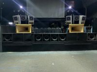
Also attached a picture of the 'big system' as it currently is.
OS throat -> conic -> tactrix derived mouth
I have access to CNC so 3 separate sections. My current plan for the B52 horns is to use them for the tweeters >4kHz in the big system with the eminence ring radiator.
I have been working on MATLAB/Octave code for composite curve horn designs as I'm designing a horn for the M200 midrange compression driver (again for the big system).
I attach another side mounted slot loaded woofer design that I have saved a picture of but am not sure where I got it from. Probably somewhere here?
Also attached a picture of the 'big system' as it currently is.
Attachments

Very nice. My first synergy prototype also lead me to an idea of OS (or Peavey quadratic style) throat milled into the driver flange, then conical section and instead of a secondary flare, large roundover milled from something like 6 x 10 cm construction wood. I would be happy to see some pictures when you have progress with this project.
(need to work out how to plot beamwidth).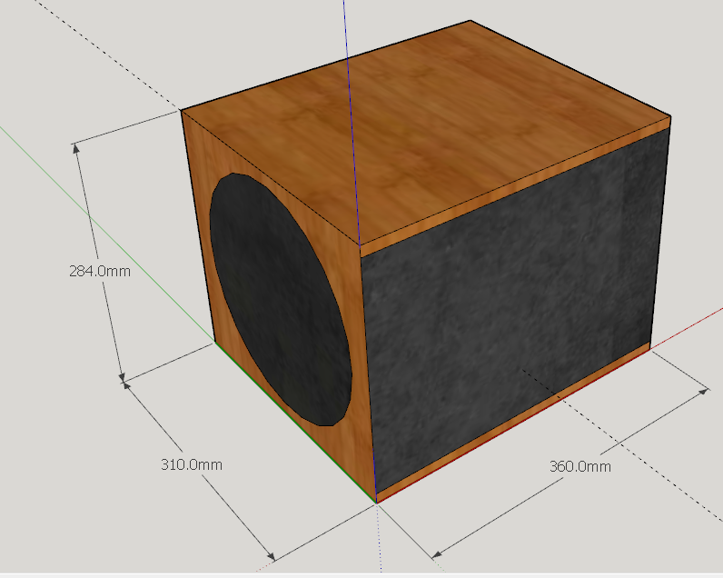
Lots of sims to work out if this is all possible!
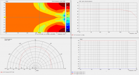
Since this had me scratching my head as well not so long ago 🙂
Then right-click the coloured contour plot:
You can also press Ctrl+M to add markers to the z-axis, and those will outline the relevant coloured edge on the contour plot:
The directivity contour will appear in the bottom right plot. This is from the zip file you attached in the first post if that saves you some bother.
If you get something odd, double click that plot and make sure it's set to the 'Real' Bode type. Sometimes it tries to plot as 'Level dB'.
As for quick and dirty checks for whether the drivers fit in the box, I actually find the Diaphragm element in Akabak to be easier for this than SketchUp. Most of the dimensions are on the manufacturer spec sheet, and the 'Standard' model it generates has a decent approximation of the magnet dimensions.
No worries. I spent a lot of hours inside Akabak over the summer for my dissertation so feel free to ask if there’s something you want help with.
I keep threatening myself with writing some sort of user guide to expand on the YouTube videos focused on HF waveguides, but probably not until the new year.
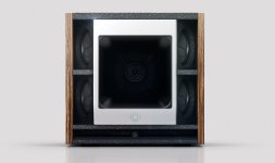
That photo on the left of one of your inspiration boxes isn’t so far off an SM100B, which is a very nice box. We’ve got a couple and people are quite surprised at the low-end response.
I keep threatening myself with writing some sort of user guide to expand on the YouTube videos focused on HF waveguides, but probably not until the new year.
That photo on the left of one of your inspiration boxes isn’t so far off an SM100B, which is a very nice box. We’ve got a couple and people are quite surprised at the low-end response.
The company behind the loudspeaker 'Square One' on the left image is Square Audio. It does not seem to exist any more. http://www.square.audio/
It had four 5.25" Scan Speak woofers and a 2" 60x40 or 90x60 deg 18Sound horn.
It had four 5.25" Scan Speak woofers and a 2" 60x40 or 90x60 deg 18Sound horn.
Last edited:
This is what I found surfing the web archive:

So it seems that this is actually possible and was done before🙂 It is really a compact box, I wonder how it would compare to a normal 3 way large Synergy horn.
So it seems that this is actually possible and was done before🙂 It is really a compact box, I wonder how it would compare to a normal 3 way large Synergy horn.
wow that's pretty close to what I imagined, good find. Is that a sound physics box from Danley?
I haven't forgot this project but I have decided to build a low SPL Hi-Fi version first for my desktop first as I don't have any computer speakers and its a good proof of concept I can build for the price of a single woofer for the high SPL version!
I haven't forgot this project but I have decided to build a low SPL Hi-Fi version first for my desktop first as I don't have any computer speakers and its a good proof of concept I can build for the price of a single woofer for the high SPL version!
Yes, it is from the archive of soundphysics.com. http://web.archive.org/web/20081204095429/http://www.soundphysics.com/SPL-C3.html
From some of the dates, the EASE data can be downloaded. I did, but I do not think I have the means to open them.
From some of the dates, the EASE data can be downloaded. I did, but I do not think I have the means to open them.
- Home
- Loudspeakers
- Multi-Way
- Compact 3 way PA 90x60 speaker (MEH + side woofers)