Hi all, looking around the web for speaker design guides (trying to go back to basics a bit) and found this. So many odd ideas, I don't want to say too much yet until others have had a chance to enjoy;
3 Way Crossover Design Example
Would love to hear your thoughts!
3 Way Crossover Design Example
Would love to hear your thoughts!
Thanks for posting that: it is great to have so much material available for us newbies.
However, that site uses crossover calculators, which are almost guaranteed not to work properly, for a host of reasons. For example, it assumes all drivers are 8 ohms: but that's a nominal 8 ohms and the impedance of the drivers and the finished speakers will vary with frequency, which affects crossover design.
You can prove that by using a program such as Xsim to see what a calculator would give you in parts values for a given speaker, and compare that to what's actually in the measured and tested design.
All that aside, we have access to materials, tools and advice that wouldn't have been dreamed of 20 years ago, and most of them are free. And there are many, many experienced designers and hobbyists who are happy to provide their expertise and time to help us, value!
Geoff
" it assumes all drivers are 8 ohms" - no, the actual calculator asks for impedance values, and is quite usable, provided you have some idea of what's going on.
'So many odd ideas' - what do you find odd? If you list them we may be able to find situations where they're not so odd, assumptions made etc.
If you want to get back to basics, Rod Elliott's articles are quite informative, but written from a theoretical standpoint rather than a practical point of view. I see so many 'you shouldn't do that' type of comments on these forums, simply because it isn't understood that sticking to purely theoretical ideals may not necessarily lead to practical outcomes.
Hi Geoff,
Thanks for the response I'm guessing it's a little tongue in cheek? I'll edit the OP when a few more people have chipped in
Not at all: this is a great hobby, there's a great deal to learn and I never cease to be knocked out by the generosity of people who are willing to share their experience, time and expertise. All my projects are other peoples' .
Geoff
My problem with those articles is that they approach crossover design from an ideal point. And this is also the fault at the base of all crossover calculators. I don't have any problem with the math, but the basics on how a crossover works is useful only if you know how to deal with real world drivers, i.e. with non flat FR and impedance. This is where a crossover simulator comes handy, something that is IMHO the great advantage we have today together with affordable measurement gear. The main problem in the DIY world is to perform reliable measurements.If you want to get back to basics, Rod Elliott's articles are quite informative, but written from a theoretical standpoint rather than a practical point of view.
Ralf
Ignoring the fact that like all XO calculators it assumes co-incident drivers with a flat on-baffle response and no impedance fluctuation from the nominal Re value other than the tweeter's Fs peak, then the topology is conventional other than the use of a fixed L-section attenuator on the bass driver. Which has been known [very occasionally] but is not generally done. I certainly wouldn't expect this circuit to work well in practice, but it depends on what the on-baffle responses are.
For anyone reading the link in the OP thinking that is an ok way to design a crossover - it is not. Textbook calculators are absolute crap.
You may as well take all the money spent on the expensive Scanspeak drivers (if you are not going to design a proper crossover) and flush it down the toilet. The noise will be more pleasant.
You may as well take all the money spent on the expensive Scanspeak drivers (if you are not going to design a proper crossover) and flush it down the toilet. The noise will be more pleasant.
Textbook v Real
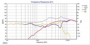
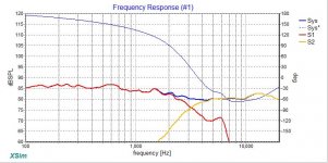
As a quick illustration of why 'textbook' calculators don't work, I've done a quick Xsim comparison of a textbook (first graph) vs properly measured and designed XO. The second XO takes the raw driver data and applies the correct XO parts, so it's not measured in box: the speaker actually has more BSC than the sim shows.
The red (tweeter) and orange lines (mid woofer) are the driver curves, the blue is the system response. You can see that the first is a real mess in terms of the drivers interfering with each other, plus it has a painful top end. Bleah, as Snoopy would think.
The calculated parts values were 6.8 cap and 0.4mH shunt inductor for the tweeter and 0.4mH and 3.3 shunt cap for the mid. The actual parts values for this speaker - which sounds really nice - are 6.8 series cap, 0.15 shunt inductor and 15 microfarad series cap plus L-Pad for the tweeter, and 1.3mH series inductor and 4.7 microfarad shunt cap for the mid.
I should add the the drivers in question are very smooth and well behaved, without peaks or resonances which need to be tamed. I won't name them as the project is the designers' intellectual property.
As an illustration of what makes this hobby so enjoyable, the project details were kindly provided to me by a well known DIY Audio member.
Geoff
Attachments
Last edited:
So I deliberately bit my lip because I hadn't taken time to pull this site apart (I hadn't even looked at the crossover calculator). I'm also very aware that I am not a degree qualified audio engineer; there's plenty of scope for me to learn.
All that said however, I'm also aware how this hobby is easy to iceberg.... So many people learn the tip and don't see the rest of what's under the water. Because of that there's a lot of beginners putting advice out there and it seems to be a case of the blind leading the blind.
For what it's worth, if you're an absolute beginner and MUST design using calculators and not measurements, ease do yourself a favour and see the sticky post
"Introduction to designing crossovers without measurement"
The only point I'd add to that is that baffle step compensation should be thought of as mandatory not optional in all speakers, but that's just my experience.
I found the linked site particularly alarming as there were a lot of odd ideas put forward as fact, and some gross errors which put me away from the benefit of the doubt category. All that said, here's a breakdown on the bits that raised an eyebrow for me:
-the author correctly points out that one octave relates to a doubling in frequency, then states that 3Hhz is in the middle of 2kHz and 4kHz.(I know I'm being a pedant on that one)
- "Some people believe that it is best to use a low order crossovers when possible, preferably only 1st order. This does have some benefits. With the greater frequency overlap, voices will not seem to jump from one driver to another as quickly as they would with a steep crossover. It also follows the minimalist approach where the simpler the circuit, the less distortion and modification of the signal is introduced"
In my opinion a true 1st order crossover is 1st order acoustic. That can require a very complex crossover to actually achieve. My experience has been that 1st order electrical is almost always motivated by the fact it's cheap and easy. The idea that voices jump from one driver to another goes against what Zaph said when he described a 2 way 6th order as being like a point source in sound. My understanding is that 1st order appeals for phase alignment reasons, however the also seems to be out on that. Also, I must say that the idea that crossover components introduce audible distortions is such a joke at this point. My experience has shown this isn't true, when something sounds wrong it has always been the crossover design not parts that have caused issue. If each component added more distortion my 22 component 3 way xo couldn't sound better than the 11 component version it replaced.
Also, the signal has to be modified in order for the speaker as a complete system to accurately reproduce it, otherwise no crossover would ever be needed.
"Another belief is that even order (2, 4, 6...) order crossovers should be avoided. Even order crossovers tend to have spikes or dips in the frequency response around the crossover point. These spikes can be as bad as -30db, but can easily be solved by reversing the polarity of only one of the speakers, limiting the spike to about +- 3db."
I read this and feel like the author has misunderstood what an even order crossover is. A 2nd order xo can theoretically have a large null if the polarity of the drivers is not reversed but since when was this a con of 2nd order designs? Further more many well respected companies swear by 4th order LR, hardly in any "should be avoided" category. My understanding is that even order crossovers are the only was to phase align driver output in the listening window (I'm open for input and discussion).I'm aware that Douglas self stated that 4th order LR is really the best crossover we can achieve at the moment, from a technical perspective, just one man's belief I know, but a man with excellent technical ability and understanding.
I would have been far more impressed with the site if it had a calculator that used the driver DCR and inductance and baffle size to make an off the shelf calculator, but when I eventually went to check what calculators they had, they were the generic nightmarish calculators that lead beginners into believing they've done everything right
The last part was the topology with the positive input for the tweeter filter coming from the positive output of the midrange HP. I've never seen anything like that (except in series xo's) and just looks horrid. Rightly or wrongly many people spend a lot of money on fancy caps for tweeter chains, if they were to do this they'd have to ensure the very large, expensive caps in the midrange filter were up to scratch. More importantly, surely this will make a Trainwreck of xo design, as the variable.impedance of the tweeter network would be visible to the midrange output, and the midrange high pass would, to some extent at least, interfere with the tweeter output?
Anyway, just my thoughts...
As another example of 'what not to do', some people use, and seem happy, with 'off the shelf' crossovers. As far as I can tell, these have the same issues as using crossover calculators.
If people are happy, fine of course, but they're missing out on rather a lot and wasting money - in some cases, a great deal of money.
For example, on another site someone has used Morel Supreme tweeters (about $500 pr) and high end Morel woofers ($ lots) and then matched them with a branded off the shelf crossover with generic driver parts values. Almost certainly, the speakers couldn't possibly sound as good as they could with a custom crossover.
I'm happy to admit that crossover design goes right over my head and I have no idea about Butterworth, LR, cabinet alignments, which order slopes to use and when, etc.
However, after building a few projects by people who know what they're doing, a lot of reading, simming and messing around with different crossover parts, I have learned a bit and enjoy my music more than before, which to me is the point of DIY.
Geoff
Briefly wading in here:
YMMV. 3KHz is the mid-point between 2KHz and 4KHz, though since he mentioned 1/2 octave 'stability' in either direction it's slightly mixed messaging / poor grammar.
To be honest, what you have there is more a difference of opinion than any factual disagreement per se. There is no industry convention about whether a crossover of x order is defined by its acoustic or electrical nature; experienced designers in discussing usually use the former while noting what electrical transfer functions were required in order to achieve it.
Regarding Zaph's remarks, some context is necessary. The enclosure you are referring to was a compact 2-way competition entry with an extremely low 1.1KHz crossover frequency (the sort of thing I favour myself as it happens). Driver spacing was well within 1-wavelength, and as I recall, bordering on 1/2 wavelength. As a result, it behaved more or less like a point-source. Moreover, this XO frequency is in a narrow region where human hearing is relatively poor at localising sound sources, even though it is relatively sensitive to amplitude variation; this also helps to some extent with the GD & significant 540 degree phase rotation inherent to LR6, which is more likely to become audible with a higher crossover frequency. Note that John (Zaph) noted elsewhere on his site that he favoured LR2 with higher crossover frequencies, noting his belief that the lower order slope sounded better due to the reduced phase shift and superior power response. I'm not entirely convinced by that argument, at least vis-a-vis LR4, although it may hold more weight when compared to higher order filters at such frequencies, less, I suspect, for reasons of overall linear phase response but for reduced GD & phase rotation at & around the XO frequency itself.
Yup.
Generally true, although some rather expensive hand-made components are so poorly made that they can in fact induce distortion, through lose winding, poor thermal properties or whatever. A good argument for quality, mass-produced components if ever there was one.
The context is questionable. Symmetrical even order Butterworth filters with the same XO frequency produce a +3dB peak; Linkwitz has the ability to sum flat in the desired polarity, but this is all theoretical and assuming coincident drivers with flat FR & impedance responses. I would presume that the remarks were meant as observation only, relative to the ability of symmetrical odd-order Butterworth filters to sum flat in either polarity (same conditions assumed), albeit at 90 degrees (+ option of 270 degrees for B3) phase separation. Some view this as an advantage; personally I regard it as an 'it is what it is' scenario as I use what best meets my design goals. LR4 is usually seen as a solid compromise, but other options can also be a solid compromise.
I wouldn't call them nightmarish: they are using the correct electrical filter values, so there is nothing to criticise in that sense. However, understanding the context and limitations of this, and the fact that most drive units are not coincident, and have significantly varying frequency and impedance responses are the key to quality XO design. So like all such calculators, or the formulas they use, they are highly limited / bordering on useless.
I have. It's sometimes done, as a convenient way of obtaining a desired transfer function for a reduced part count (and cost) as you have at least one component pulling double-duty. You'd struggle to create such a filter design with that on-line calculator") but it's not unknown, taken as a broad concept. That doesn't mean the filter as-designed is any good of course...
but it's not unknown, taken as a broad concept. That doesn't mean the filter as-designed is any good of course...
-the author correctly points out that one octave relates to a doubling in frequency, then states that 3Hhz is in the middle of 2kHz and 4kHz.(I know I'm being a pedant on that one)
YMMV. 3KHz is the mid-point between 2KHz and 4KHz, though since he mentioned 1/2 octave 'stability' in either direction it's slightly mixed messaging / poor grammar.
- "Some people believe that it is best to use a low order crossovers when possible, preferably only 1st order. This does have some benefits. With the greater frequency overlap, voices will not seem to jump from one driver to another as quickly as they would with a steep crossover. It also follows the minimalist approach where the simpler the circuit, the less distortion and modification of the signal is introduced"
In my opinion a true 1st order crossover is 1st order acoustic. That can require a very complex crossover to actually achieve. My experience has been that 1st order electrical is almost always motivated by the fact it's cheap and easy. The idea that voices jump from one driver to another goes against what Zaph said when he described a 2 way 6th order as being like a point source in sound.
To be honest, what you have there is more a difference of opinion than any factual disagreement per se. There is no industry convention about whether a crossover of x order is defined by its acoustic or electrical nature; experienced designers in discussing usually use the former while noting what electrical transfer functions were required in order to achieve it.
Regarding Zaph's remarks, some context is necessary. The enclosure you are referring to was a compact 2-way competition entry with an extremely low 1.1KHz crossover frequency (the sort of thing I favour myself as it happens). Driver spacing was well within 1-wavelength, and as I recall, bordering on 1/2 wavelength. As a result, it behaved more or less like a point-source. Moreover, this XO frequency is in a narrow region where human hearing is relatively poor at localising sound sources, even though it is relatively sensitive to amplitude variation; this also helps to some extent with the GD & significant 540 degree phase rotation inherent to LR6, which is more likely to become audible with a higher crossover frequency. Note that John (Zaph) noted elsewhere on his site that he favoured LR2 with higher crossover frequencies, noting his belief that the lower order slope
My understanding is that 1st order appeals for phase alignment reasons, however the also seems to be out on that.
Yup.
Also, I must say that the idea that crossover components introduce audible distortions is such a joke at this point. My experience has shown this isn't true, when something sounds wrong it has always been the crossover design not parts that have caused issue. If each component added more distortion my 22 component 3 way xo couldn't sound better than the 11 component version it replaced.
Generally true, although some rather expensive hand-made components are so poorly made that they can in fact induce distortion, through lose winding, poor thermal properties or whatever. A good argument for quality, mass-produced components if ever there was one.
"Another belief is that even order (2, 4, 6...) order crossovers should be avoided. Even order crossovers tend to have spikes or dips in the frequency response around the crossover point. These spikes can be as bad as -30db, but can easily be solved by reversing the polarity of only one of the speakers, limiting the spike to about +- 3db."
I read this and feel like the author has misunderstood what an even order crossover is. A 2nd order xo can theoretically have a large null if the polarity of the drivers is not reversed but since when was this a con of 2nd order designs? Further more many well respected companies swear by 4th order LR, hardly in any "should be avoided" category.
The context is questionable. Symmetrical even order Butterworth filters with the same XO frequency produce a +3dB peak; Linkwitz has the ability to sum flat in the desired polarity, but this is all theoretical and assuming coincident drivers with flat FR & impedance responses. I would presume that the remarks were meant as observation only, relative to the ability of symmetrical odd-order Butterworth filters to sum flat in either polarity (same conditions assumed), albeit at 90 degrees (+ option of 270 degrees for B3) phase separation. Some view this as an advantage; personally I regard it as an 'it is what it is' scenario as I use what best meets my design goals. LR4 is usually seen as a solid compromise, but other options can also be a solid compromise.
I would have been far more impressed with the site if it had a calculator that used the driver DCR and inductance and baffle size to make an off the shelf calculator, but when I eventually went to check what calculators they had, they were the generic nightmarish calculators that lead beginners into believing they've done everything right
I wouldn't call them nightmarish: they are using the correct electrical filter values, so there is nothing to criticise in that sense. However, understanding the context and limitations of this, and the fact that most drive units are not coincident, and have significantly varying frequency and impedance responses are the key to quality XO design. So like all such calculators, or the formulas they use, they are highly limited / bordering on useless.
The last part was the topology with the positive input for the tweeter filter coming from the positive output of the midrange HP. I've never seen anything like that (except in series xo's) and just looks horrid.
I have. It's sometimes done, as a convenient way of obtaining a desired transfer function for a reduced part count (and cost) as you have at least one component pulling double-duty. You'd struggle to create such a filter design with that on-line calculator
but it's not unknown, taken as a broad concept. That doesn't mean the filter as-designed is any good of course...- Status
- This old topic is closed. If you want to reopen this topic, contact a moderator using the "Report Post" button.
- Home
- Loudspeakers
- Multi-Way
- Have to love the beginner guides out there.