True, and I can see that in the measurements, sonograms and decay plots. One box firing into the other in opposite polarity does change the panel resonances. Mostly in the bass of course, but it also changes harmonics and decay time.The two cabinets will be creating a more complex and quieter radiation pattern than a single cabinet...
That said, the changes I saw don't diminish the usefulness of the technique by much. It's just something to be aware of. To get more precise results a contact mic or accelerometer is helpful.
Indeed. At the risk of dampening enthusiasm can I suggest a bit of basic checking?
The expected behaviour for an arrangement like this is:
- large cancellation of fundamental
- enhancement and reduction of harmonics
- degradation due to differing driver parameters
- sound from the baffle
- some form of cavity resonance
So measure to see to what degree this is occurring. Perform a typical measurement including harmonics. Place the microphone close to the gap and check that you are measuring mostly enhanced and reduced harmonics as expected.
If you are getting good cancellation then place something like a door sealing strip, stiff foam, rubber,... around the outside of the baffle in order to seal the gap with minimal influence on the cabinet motion.
The two cabinets will be creating a more complex and quieter radiation pattern than a single cabinet and, more importantly, the radiation from the baffle will be missing. This is normally the most important because it is hammered on by the heavy drivers, weakened by holes being cut out and radiates sound directly at the listener.
So place a microphone close to a panel (or contact microphone on panel) and check you are measuring as expected a typical cabinet response (see BBC, KEF and others for examples). That is, a few high Q resonances. Do not average the frequency bins because it destroys this information. Use a fine resolution in frequency and ensemble average if possible.
If you are getting what is expected then move towards the far field and check you are still seeing cabinet radiation. That is, high Q resonances and possibly cancellation dips.
Now that we know that it can be done, we have to figure out a more refined protocol, so this is very good input. Everything you're bringing up makes total sense.
Last edited:
I think the original plan Jim proposed is better. Not by destroying a driver, but by using a bass shaker as a source. Now these sure have acoustic output. Using a long rod to connect it to the box (the Clark shakers seem perfect for that) and muffling the shaker itself could bring some. Now I don’t have a shaker lying around...
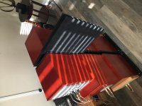
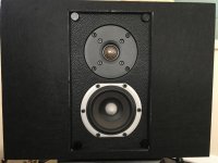
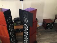
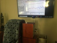
My original idea involved doing it this way(before the thick blanket idea). High density acoustic felt placed between, to the side and perpendicular to the panels. Using both methods at the same time should go a long way toward addressing some of the concerns brought up. As you can see by the photo, they're wedged between the baffles. this will soak up a lot of the stray audible crap that might be escaping. You could even make a cutout for the drivers on the felt that would address the issue around the entire circumference of the speaker baffle.
Attachments
Last edited:
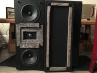
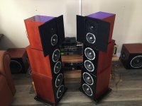
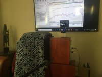
I am going to cut a hole in the felt pieces for the drivers to allow the felt to completely “seal”around the baffle to attenuate as much as possible any stray noise that can escape. The hole will be just large enough for the 4” midbass units. Then I’ll take more measurements and see if there’s a difference. It’s funny, but the Dunlavy’s are already set up that way.
Attachments
Last edited:
If you flush-mount or even rear-mount a speaker into a 4’x8’ piece of plywood, you can use baffle step to eliminate rear output above the (very low) baffle step frequency. As long as the plywood is somewhat decoupled, or stiffened dramatically to prevent adding any new resonances to the system that didn’t exist before

As I did my quick-and-dirty experiment, I was regretting that I did not have a piece of melamine foam... 10" x 12" x 1" would have been nice... I would have cut a 7" hole in the middle for the two drivers to radiate into, and sandwiched the foam between the two cabinets.
Pano - when you ran just one speaker and took measurements with the contact mic, is it possible you were picking up acoustically transmitted energy, in addition to structure-born energy? I don't know much about contact mics. But if your contact mic is picking up a small amount of acoustic energy, that could explain why we see an ~ 8 dB drop when both speakers are running and creating a cancellation null.
I am hoping this method will provide a conservative estimate of cabinet radiation... i.e. we will be able to say that the cabinet radiation is no worse than X, it could be less, but it is no higher than X. But your finding needs to be run to ground and explained before we can make that assertion.
Andy - your concern about baffle radiation... that is a tough one to solve. I can't think of a good way to isolate baffle radiation from driver radiation.
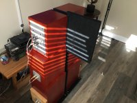
One down, one to go. The “wings” will help isolate one side’s panel output from the other.
I had to make the cutout larger to accommodate the ‘removable baffle’ caps.
https://images-na.ssl-images-amazon.com/images/I/61E0+waYXjL._AC_SY450_.jpg
Because the felt will be "edge on" relative to the drivers, the absorption should be pretty effective. It will have to pass through about an inch of the high density felt before reaching the baffle edge, so the absorption coefficient should extend a little deeper than just the 3/8" material.
Attachments
Last edited:
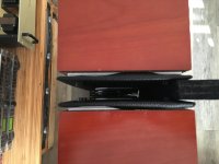
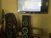
All done. The next set of measurements will all be identical in every way except for “with” and “without” the felt. Measurement mic distance(12”)and amplitude will be identical for all. The tweeters will be shut off and the mid-bass’s will be run wide open
Attachments
Last edited:

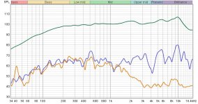
Okay, here they are. Orange trace is with felt(With a tight seal), blue is without felt. Surprisingly little change where it actually matters. So this measurement can be done without felt, as long as you have good to excellent driver pair matching to begin with. What's happening above 1.5khz is probably just the felt absorbing the high frequencies that weren't getting nulled effectively to begin with.
Attachments
Last edited:
I think what the measurements are saying is that under 1.5khz, the null was good to begin with and the felt has little left to clean up. These 4" drivers have very little output below 100hz, so they're not the best candidates for stimulating below 100hz resonances.
Last edited:
So trying to understand where this thread is really going. It started with Headunit asking about accelerometers to measure vibration in enclosures. That makes sense to me. Identify vibrations and experiment with bracing/dampening and remeasure. Are you guys trying to measure side panel vibrations acoustically with a mic and therefore need to dampen direct speaker output. Why not just use an accelerometer to start with.
Indeed. It's just another method for looking at things. I've been doing my best posting contact mic measurements and even the flaws of that device.
If someone here has an accelerometer to use and post results, we'd love to see it. I hope that it will be more linear than my contact mic, and have less pick up thru the air.
If someone here has an accelerometer to use and post results, we'd love to see it. I hope that it will be more linear than my contact mic, and have less pick up thru the air.
Are you picking up here, or have you been following the several pages? It sounds like you read the first few posts and the last few posts in this thread and made a comment based on just that. Go back to post 128, read forward from there and then make a comment.So trying to understand where this thread is really going. It started with Headunit asking about accelerometers to measure vibration in enclosures. That makes sense to me. Identify vibrations and experiment with bracing/dampening and remeasure. Are you guys trying to measure side panel vibrations acoustically with a mic and therefore need to dampen direct speaker output. Why not just use an accelerometer to start with.
Last edited:
So if you reference post #105 in this thread you can get everything you need for under $100 dollars. The amount of time you will save yourself vs. acoustic measurements is well worth the money. An excellent measurement system that I used many times to detect minute vibrational anomalies in SOA coating applications (thinfilm)
Maybe stick a tactile transducer (Exciters & Tactile Transducers - Parts Express) on the back of a driver's magnet, drive the TT instead, and measure the acoustic output of the cabinet? I always thought about trying that, but never got to it. It would only be good for comparative tests (with/without bracing, damping, isolators) though I imagine.
- Home
- Loudspeakers
- Multi-Way
- Accelerometers to measure panel vibrations?