I've started a new project of building a pair of floor-standing speakers. They're 3-way with 4 drivers per cabinet; 2 x 8" woofers + a 3" midrange + a 1" tweeter.
Tweeter: Scan-Speak D2604/833000
https://www.scan-speak.dk/datasheet/pdf/d2604-833000.pdf
Midrange: Vifa D75MX-41
https://audio-hi.fi/download/pdf/Vifa_D75MX41-08_dome_midrange.pdf
Woofer: ADS 308RS (automotive subwoofer)
fs = 34.3 Hz
Vas = 1.02 ft^3
Qts = 0.35
Qes = 0.42
Qms = 2.20
Sd = 33.9 in^2
Sensitivity = 92 dB
Re = 4.3 Ohms each (8.6 Ohms in use with series wiring)
Im = 4.0 Ohms each (8.0 Ohms in use with series wiring)
Xmax = +/- 0.32"(linear) to +/-0.47"(peak)
Volume of air displaced by woofer = 0.048 ft^3
Cabinet dimension: Height = 110 cm., Width = 26.5 cm., Depth = 30 cm.
Each woofer has its own sealed chamber, dividing 2 rooms by halving the height of cabinet. Resulting in about 1.5 cu.ft. for each woofer and Qtc = 0.34.
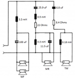
Crossover network: 2nd-order in every section, see attached picture.
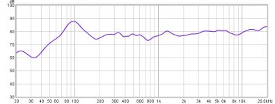
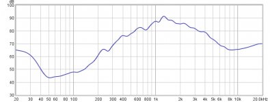
The problem I found now is poor tonal balance. The sound was too bright and pronounced midrange, and the woofers had too low SPL. I'd tried to put the larger resistors on midrange and tweeter but it didn't help. The measurement is on attached. Could anyone help to suggest me please?
Note 1: Reference level is so low due to the woofer's SPL. 😕
Note 2: Peak at 100Hz is due to room acoustics, please ignore it.
Tweeter: Scan-Speak D2604/833000
https://www.scan-speak.dk/datasheet/pdf/d2604-833000.pdf
Midrange: Vifa D75MX-41
https://audio-hi.fi/download/pdf/Vifa_D75MX41-08_dome_midrange.pdf
Woofer: ADS 308RS (automotive subwoofer)
fs = 34.3 Hz
Vas = 1.02 ft^3
Qts = 0.35
Qes = 0.42
Qms = 2.20
Sd = 33.9 in^2
Sensitivity = 92 dB
Re = 4.3 Ohms each (8.6 Ohms in use with series wiring)
Im = 4.0 Ohms each (8.0 Ohms in use with series wiring)
Xmax = +/- 0.32"(linear) to +/-0.47"(peak)
Volume of air displaced by woofer = 0.048 ft^3
Cabinet dimension: Height = 110 cm., Width = 26.5 cm., Depth = 30 cm.
Each woofer has its own sealed chamber, dividing 2 rooms by halving the height of cabinet. Resulting in about 1.5 cu.ft. for each woofer and Qtc = 0.34.
Crossover network: 2nd-order in every section, see attached picture.
The problem I found now is poor tonal balance. The sound was too bright and pronounced midrange, and the woofers had too low SPL. I'd tried to put the larger resistors on midrange and tweeter but it didn't help. The measurement is on attached. Could anyone help to suggest me please?
Note 1: Reference level is so low due to the woofer's SPL. 😕
Note 2: Peak at 100Hz is due to room acoustics, please ignore it.
Attachments
Last edited:
The Re of the Woofer: ADS 308RS is only 4.3 Ohms maybe the voltage of your amplifier is not enough 8 Ohm could be a better choice.
The Re of the Woofer: ADS 308RS is only 4.3 Ohms maybe the voltage of your amplifier is not enough 8 Ohm could be a better choice.
Sorry, I didn't mention. The woofers were dual voice coils. So, the impedance or resistance were doubled to approx. 8 Ohms with series wired the two voice coils together while installation.
.........OK, in your wiring diagram you paralleled them back to ~4 ohms, same as the tweeter, but the mid is 8 ohm, so needs at least a resistor in parallel to drop it down, then re-do the XOs to improve tonal balance with the understanding that due to baffle step loss, may need to shelve down the mids/HF up to -6 dB depending on room acoustics, speaker, 'sweet spot' placement: General Speaker Related Articles
If your amp can't handle this complex, low resistance load, then need an in-line power resistor to preload the amp, allow you to better tonally balance them and of course long term need to replace it to get back this lost efficiency and switch to higher efficiency 4 ohm woofers in series for max practical efficiency, re-do the filters or better, switch to DSP.
GM
.........OK, in your wiring diagram you paralleled them back to ~4 ohms, same as the tweeter, but the mid is 8 ohm, so needs at least a resistor in parallel to drop it down, then re-do the XOs to improve tonal balance with the understanding that due to baffle step loss, may need to shelve down the mids/HF up to -6 dB depending on room acoustics, speaker, 'sweet spot' placement: General Speaker Related Articles
Sorry, I don’t understand why the mid should be changed its impedance to 4 ohms to be the same as woofers and tweeter? Also, whether a single resistor directly paralleled to the driver might be a disaster for it as it would have to handle the same amount of power as the driver it paralleled to, and how about the heat dissipating? Does it need to use a fairly large wattage resistor?
And for the baffle step compensation, without using it, as it require to make new cabinets, is it possible to use a common series-resistor-to-driver method as being used instead?
Last edited:
If you really connected the coils in parallel that would give 2 Ohm, not 4. Nice amp load 😀 or the scheme is wrong or your measurements are not performed with the setup for your listening. 3m5 on a 2 Ohm load is kind of a low lowpass. Would explain the hump at 100Hz though. And car subs have high coil inductance too, that adds up.
Last edited:
If you really connected the coils in parallel that would give 2 Ohm, not 4. Nice amp load 😀 or the scheme is wrong or your measurements are not performed with the setup for your listening. 3m5 on a 2 Ohm load is kind of a low lowpass. Would explain the hump at 100Hz though.
I had checked the impedance already with meter before making crossover. The woofers were really 8 ohms each, with parallel configuration, it yielded 4 ohms total for woofers section.
The 100Hz hump always existed for whatever speaker tested. So, I considered its as room effect.
When crossing to a mid like the Scan 75mm dome, 3.5mH on 8 Ohm seems strange to me. Aim at 700Hz or higher for the highpass of the dome. And what Le do the voice coils have?
Last edited:
When crossing to a mid like the Scan 75mm dome, 3.5mH on 8 Ohm seems strange to me. Aim at 700Hz or higher for the highpass of the dome. And what Le do the voice coils have?
I'm not sure whether you mean Le of woofers or midrange. However, the specs of midrange didn't show Le, also for the woofers. Unfortunately, I don't have the equipments to measure for it. I don't think it would be important, still, I'm unsure about it.
I thought the resistor used in midrange was too high - yes, 22 ohms - I rarely see it in any commercial speakers as well. I replaced the resistors from the stocks I had; 22 to 6.2 Ohms for midrange and 8.4 to 3.7 Ohms for tweeter. And I could fixed some tonal problems. The former thin and dry sound changed to louder but smoother voice! What an amazing discovery. Yet, it was just the beginning not the final answers, after listening for a few tracks, I was still fatique.
All in all, I'm still finding the solutions to establish the good tonal balance. Does anybody have a trick to choose the resistors in setting a tonal balance?
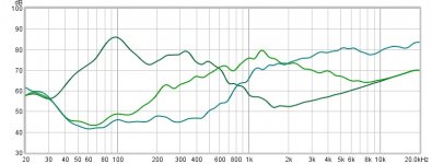
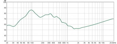
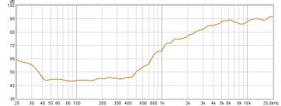
Here I have posted the measurements of each driver with its crossover but without any attenuating resistors.
All in all, I'm still finding the solutions to establish the good tonal balance. Does anybody have a trick to choose the resistors in setting a tonal balance?
Here I have posted the measurements of each driver with its crossover but without any attenuating resistors.
Attachments

Last edited:
I'm concerned that each measurement shows a response that rises smoothly towards 20kHz, even from drivers where I wouldn't expect that to be the case.
Given the (IMO) unreliable measurements, that should be addressed first, before any further changes are made.
Chris
Given the (IMO) unreliable measurements, that should be addressed first, before any further changes are made.
Chris
I can’t find the sub driver spec online but using a car sub for 3 way home audio doesn’t seem like a good idea. I would find different bass drivers. Two 4 ohm in series to get 8 ohm. Dual coils only complicate and especially two 4 ohm dual coil driver will allow you to have 4 or 16 ohm only, both not suited for home audio. Your best bet right now is to use only one coil on each and serial connect for a total 8 ohm. The “spare” coils will then just be unused, in any case you will struggle to have a sensitive system with a car sub in closed box I assume it’s like 85dB/w @ 50Hz and no midbass up to the dome midrange these are not well selected driver combo at all.
Last edited:
I agree with Chris above. Can you please do a FR sweep (measurement) of each driver individually (without any crossover) and tell us what gating you were using (with associated impulse response). Also make clear which graph corresponds to which driver.
We need to understand all the little mistakes if we are to help you with your goal.
We need to understand all the little mistakes if we are to help you with your goal.
Sorry, I don’t understand why the mid should be changed its impedance to 4 ohms to be the same as woofers and tweeter? Also, whether a single resistor directly paralleled to the driver might be a disaster for it as it would have to handle the same amount of power as the driver it paralleled to, and how about the heat dissipating? Does it need to use a fairly large wattage resistor?
And for the baffle step compensation, without using it, as it require to make new cabinets, is it possible to use a common series-resistor-to-driver method as being used instead?
Maybe no longer an issue, but in my time an amp wanted to 'feel' a balanced load WRT basic tonal balance, then tone controls [L pads] were used to fine tune them or some fixed version as part of the XO.
If DSP, then one can cobble up whatever's available and frequency shape it, though in all cases, base efficiency will be dictated by the bass response.
No, for a given power it's divided based on frequency, though if it was a high current draw driver regularly driven at max power it would require a proper power resistor and theoretically require factoring in any extra cab volume [Vb] to cool it or mount it outside; ditto any amp preloading resistor
Yes, I never made a BSC filter like used nowadays, I built it into the cab alignment since it's an acoustic problem and/or 'voiced' the speaker 'in situ' with amp tone controls and/or a cheap 25 ohm pot, then replaced it with a fixed resistor.
GM
I'm not sure whether you mean Le of woofers or midrange. However, the specs of midrange didn't show Le, also for the woofers. Unfortunately, I don't have the equipments to measure for it. I don't think it would be important, still, I'm unsure about it.
I just reread the topic. You have 3m5H on a 4Ohm load, probably with another 1 to 2mH due to the inductance of the woofer coils. That, with the cap you picked, leads to a lowpass somewhere under 200Hz. That is nowhere a match for your Vifa/Scan mid dome, trust me. I can imagine why you have no mids (200 to 800Hz).
Come to think of it, the hump around 100Hz likely is from your woofers. Why would it be your room?
Last edited:
Come to think of it, the hump around 100Hz likely is from your woofers. Why would it be your room?
I did the FR sweeps on many speakers, both diy and commercial, and I got a hump around 100Hz on every measurement despite no bass spike heard in real use. So, I assumed it might be results from the room.
Last edited:
The lowest the D75MX will cross and still play cleanly at elevated listening levels is about 800Hz.
The car sub is at best probably only clean to ~500Hz, probably more like ~300Hz. If the 92dB sensitivity is at 2.83V instead of 1Watt and is measured in a 2ohm configuration, then the 2.83V sensitivity at 8ohm is 80dB which could explain the unexpectedly low sensitivity.
A decent 8" midwoofer which will play cleanly to ~800Hz and has closer to 90dB/2.83V sensitivity will be a better match if you plan to run the mid and tweeter without significant padding resistors.
Last edited:
I just reread the topic. You have 3m5H on a 4Ohm load, probably with another 1 to 2mH due to the inductance of the woofer coils. That, with the cap you picked, leads to a lowpass somewhere under 200Hz. That is nowhere a match for your Vifa/Scan mid dome, trust me. I can imagine why you have no mids (200 to 800Hz).
Come to think of it, the hump around 100Hz likely is from your woofers. Why would it be your room?
Good to know, I never bothered to learn XO design beyond using basic formulas, so can't spot these sort of issues without using an XO designer to view them, just thought I'd get something going with what looked like very basic issues.
Looking at the Vifa's 300 Hz Fs, tiny Xmax, minimum XO needs to be x1.4142 = ~425 Hz/4th and preferably 600 Hz/2nd, so surprised it didn't bottom out even at fractional power.
Can't find any info on the woofer's response, so assuming the quoted specs are right, its T/S parameters ends at ~2*31/0.35 = ~196 Hz or a bit lower with wiring losses, making me wonder if it goes high enough to even blend at ~425-600 Hz.
GM
I would say that, actually, the design of my crossover was based on a commercial speaker. It was ADS L1590. I don’t know why they crossed the woofer at so low point together with the use of only 2” mid-dome. The other models use the same configuration; dual 8-10” woofers + 1.5”-2” mid-dome, as well. The woofers usually got an inductor up from 2.5 mH to 4.0 mH while the midrange got 1 mH up to 2.6 mH. This would result in gaps between the drivers. Maybe it was an adding an equalization to their builds.
- Home
- Loudspeakers
- Multi-Way
- Could I have comments on my design?