Purchased a bare bones Fusion 12 kit from DIYSG back in August 2020. Erich was able to provide me with a list of crossover parts but no photo or schematic of the crossover. My last email response from him was in August when he stated that he would provide some sort of assembly instructions for the crossovers. Have emailed several times since then but no response.
Wonder if anyone would be willing to share this information, privately of course. Would like to run this by Erich but I would not be asking for this if I were able to get in contact with him.
Not trying to be a pain, and I know Erich has been busy moving. My guess is he has not been able to come up with this info and is too busy to research it at present.
Any help would be appreciated
Charles Sedivy
csedivy22@gmail .com
Hi Chuck
The network won't be difficult to figure out if you tell us the values ( or not ) of the parts you've bought.
I'm not sure why this shouldn't become open source now that JeffB. has passed away and the F12 ( Tempest ) has been superseded by the HTM line.
A quick overlook shows ( essentially ) a 3 over 3 ( poles ) with a handful of 2 ohm resistors ( 4 in total ) modifying horn level as well as modifying the Q's of the second pole in each leg ( both HF + LF) .

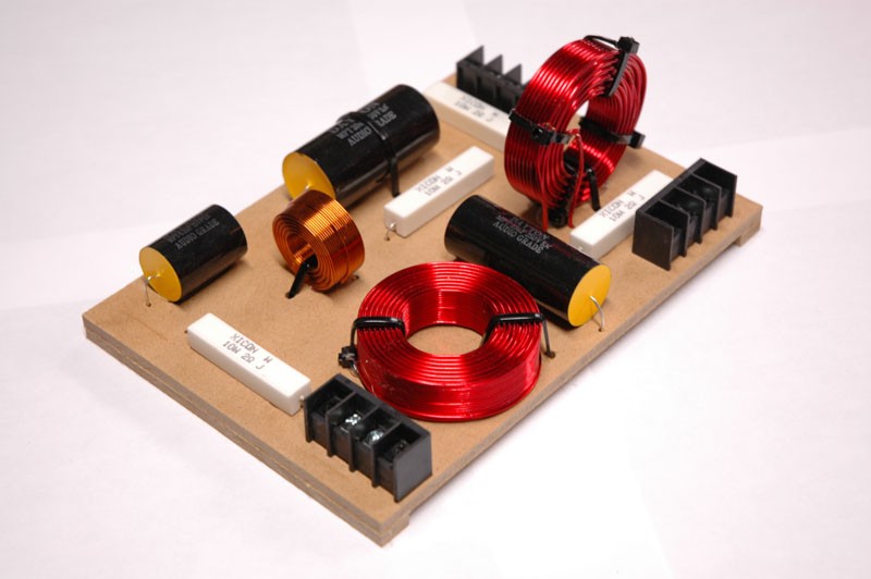
I have enough pics of the network to publish a partial schematic ( where you get to fill in the unknowns based on "best practices + a bit of logic" ) .
- ( the second pic displayed above quite clearly "telegraphs" the wiring order of the parts layout )
🙂
The network won't be difficult to figure out if you tell us the values ( or not ) of the parts you've bought.
I'm not sure why this shouldn't become open source now that JeffB. has passed away and the F12 ( Tempest ) has been superseded by the HTM line.
A quick overlook shows ( essentially ) a 3 over 3 ( poles ) with a handful of 2 ohm resistors ( 4 in total ) modifying horn level as well as modifying the Q's of the second pole in each leg ( both HF + LF) .
I have enough pics of the network to publish a partial schematic ( where you get to fill in the unknowns based on "best practices + a bit of logic" ) .
- ( the second pic displayed above quite clearly "telegraphs" the wiring order of the parts layout )
🙂
Attachments
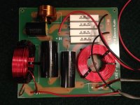

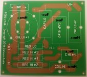
Thanks for your reply. Am attaching a photo of the crossover board I purchased overlaid with what I think are the correct locations for the components.
Most of the parts seem to suggest their locations by size as outlined on the circuit board.
The two large coils are similar in size. Based on diagrams of third order networks I have examined, the larger of the coils would be located first in series, closest to the input.
Your assistance is appreciated.
Chuck Sedivy
Attachments
Hi Chuck,
Yes, you've placed/located the caps + coils correctly.
( The resistors are of course a "no-brainer" since they all have the same value in my pictures ).
🙂
Yes, you've placed/located the caps + coils correctly.
( The resistors are of course a "no-brainer" since they all have the same value in my pictures ).
🙂
Here's the schematic as I understand it ( with FR ) using some available frds and zmas ( traced from available files ).
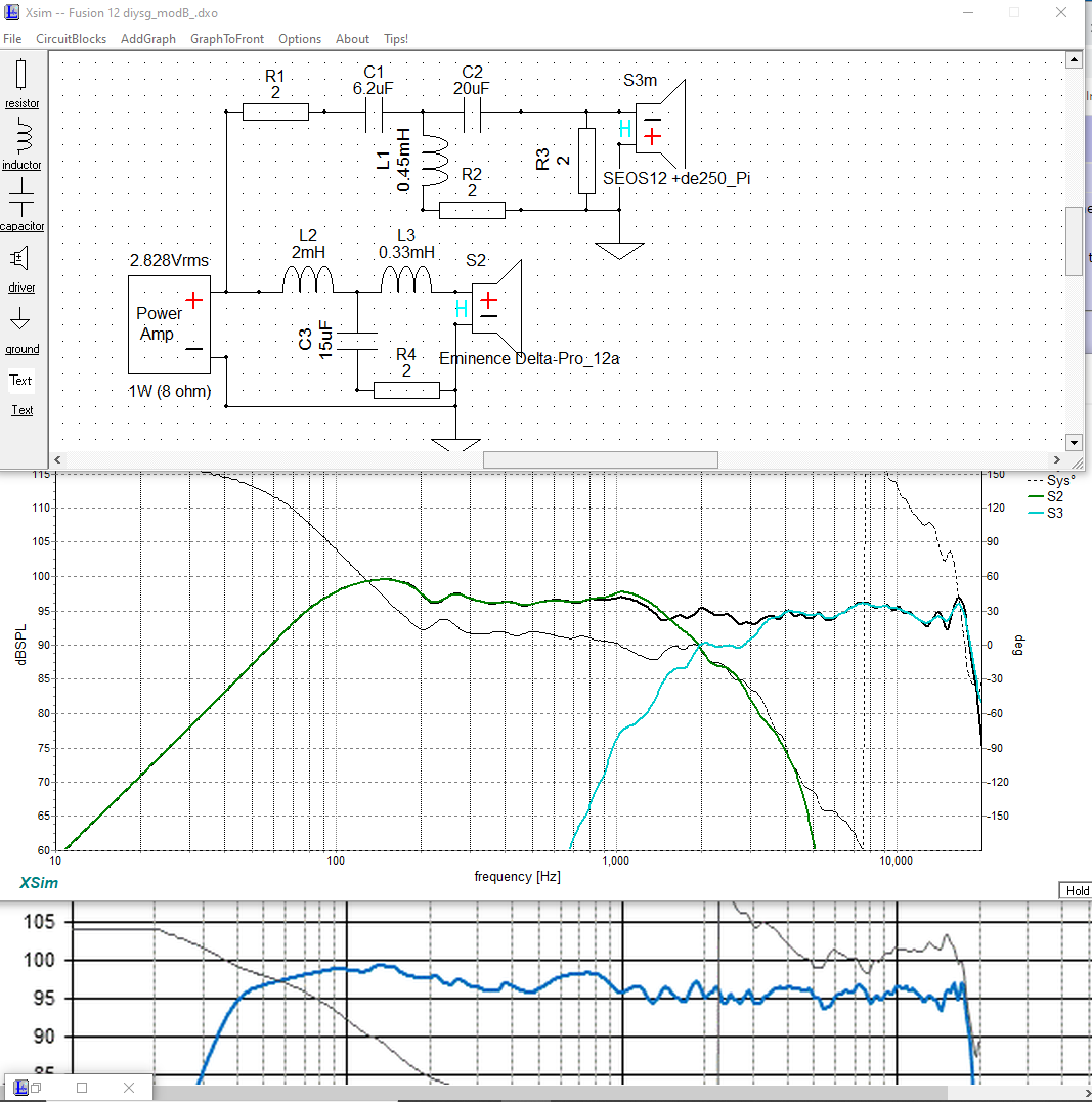
One can see that ( even with "borrowed" frd + zma files ) the response tracks quite well when compared to the official diysg response info ( seen at the bottom of my pic ).
🙂
PS, offset was set so that the horn drivers acoustic center is 3" behind the woofers.
One can see that ( even with "borrowed" frd + zma files ) the response tracks quite well when compared to the official diysg response info ( seen at the bottom of my pic ).
🙂
PS, offset was set so that the horn drivers acoustic center is 3" behind the woofers.
Attachments
Last edited:
Hi, I believe that the schematic for the hi pass
is mostly correct except there is no resister below the
.45mh inductor. Just put the 2 ohm resistor after
the 20uf capacitor in series. Also Jeff Bagby
ran positive polarity on the tweeter.
is mostly correct except there is no resister below the
.45mh inductor. Just put the 2 ohm resistor after
the 20uf capacitor in series. Also Jeff Bagby
ran positive polarity on the tweeter.
bathtub,
After staring much longer at the crossover board pic provided by Chuck, I must agree.
That makes the schematic look something like this;

This arrangement works very well as long as there's "little to no Acoustic Offset" between the woofer and horn-driver ( I had to guess at a typical number for a waveguide ).
This version also has better phase tracking ( something JB definitely worked at optimizing ).
🙂
After staring much longer at the crossover board pic provided by Chuck, I must agree.
That makes the schematic look something like this;
This arrangement works very well as long as there's "little to no Acoustic Offset" between the woofer and horn-driver ( I had to guess at a typical number for a waveguide ).
This version also has better phase tracking ( something JB definitely worked at optimizing ).
🙂
Attachments
Last edited:
Thanks Earl
I am glad you confirmed this. I have starred at the schematic for the Jeff's Fusion Tempest many times on the internet since I have almost the same configuration.
I have the B&C de250 instead of the Denova driver.
I use xsim myself but I'm not nearly as proficient as you are in it. So how do you derive the offset ?
I can't actually derive the offset without having the drivers in hand.
I typically use a 2-chnl soundcard with the right chnl looped back into itself.
This setup provides a "zero" reference point.
Then ( using REW ) I measure each driver independently in box + without any filtering in place ( also, without moving the test mic between test runs ).
REW automatically spits out a distance measurement ( time of flight ) in milliseconds and/or meters/feet for each test subject .
At this point it's a simple bit of subtraction to get the offset.
🙂
Earl,
Thanks for your reply.
I use omnimic and dats. I struggle getting the steps correct. I wish Parts Express would do a course on the proper use of these tools.
Thanks for your reply.
I use omnimic and dats. I struggle getting the steps correct. I wish Parts Express would do a course on the proper use of these tools.
Setting offsets is typically for experimentation like this. You shouldn't need to set an offset for a real crossover, measuring it instead is the direct way. This means having the timing set the same for each measurement.
Another misleading situation that suggests the need for an offset, is active crossovers. Some don't have the infinite options that passives have, and therefore need to add things like delay to make them work.
Another misleading situation that suggests the need for an offset, is active crossovers. Some don't have the infinite options that passives have, and therefore need to add things like delay to make them work.
- Home
- Loudspeakers
- Multi-Way
- Fusion Tempest 12 crossover