https://patentimages.storage.googleapis.com/bf/9c/5d/00ddf4f6572e3d/US5526456.pdf
Pre dates the Sound physics lab patent by 3 years:
US6411718B1 - Sound reproduction employing unity summation aperture loudspeakers
- Google Patents
I think the Heinz patent is describing a diffraction slot structure as it talks about keeping the horizontal walls parallel in the common throat area.
there is also a patent claim:
"The loudspeaker of claim 1, wherein said first coupling and third coupling passages located on either side of passage has a maximum width spacing of less than the said first coupling passage, said second and third cou minimum wavelength of the sound being transmitted."
very interesting as I have been thinking about ways of reducing the driver count on unity horns to make them lighter/more compact and the coaxial mounting method in figure 8. would work with off the shelf drivers and DSP delay if the woofer and tweeter where swapped.
That's an interesting variation, and fairly complex. Did R-H ever sell designs like this? I haven't seen them.
I have seen large side entry horns where the throat is basically a slot. Don't know who made them.
I have seen large side entry horns where the throat is basically a slot. Don't know who made them.
The reverse type of "coaxial" makes more sense in a/for a compact system where you need more dB in the bass section. Makes sense.
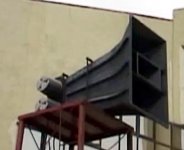
Pano that side entry horn looks a lot of like the "offset driver" horn you can model in Hornresp. This is also how the midranges/bass drivers can be modeld on a Synergy/unity horn. I guess the horn is hyperbolic so low inital flare rate?
A weakness of Synergy horns is that the mid and bass drivers have quite limited bandwidth due to this mounting arrangement. For example in my effort the mids are only covering 500HZ-1.27Khz there are just a lot of factors that limit the upper and lower frequency. This has made making two way unity horns tricky without using 'special' (expensive) drivers like coaxial compression drivers. Another issue is that the horn gain 'seen' by the mid/bass drivers at the lower end of their range is not as a traditional front loaded horn.
I see the RH design as two close to ideal FLH with the bass horn entering the tweeter diffraction slot at the point the cross sectional area matches, so the bass driver as its just seeing a conventional horn should have wider bandwidth and better efficiency.
Looks like R-H do or did, sell some speakers based on that patent. They call them CoEntrant.
https://www.renkus-heinz.com/core-technologies
https://www.renkus-heinz.com/core-technologies
Attachments
I'm no expert of course but I'll read the Renkus-Heinz patent. I have some familiarity with Danley's stuff, actually owning a used pair of Unities and I've driven to the factory to hear a 15 minute demo 🙂 Curiously, I see the patent you list was assigned to Sound Physics, which was Danley's employer at time (?) or at least made early Unity speakers. The finer differences on these inventions escape me, but I guess you have to be skilled in the art 🙂
I goofed above, assuming the linked patent was for R-H. A closer reading explains why it was assigned to Sound Physics 😀
Kipman said:
"Another issue is that the horn gain 'seen' by the mid/bass drivers at the lower end of their range is not as a traditional front loaded horn".
How does it differ? The Unity horn mid/bass are put at a distance that is optimally within the 1/4 wavelenth to throat but also the correct wave-launch (?) distance. Isn't the lenth of the waveguide the determinant on how low the horn loading goes?
There are two patent links. The first one is the R-H patent. I also clicked on the second one and thought the same thing. 🙂ICuriously, I see the patent you list was assigned to Sound Physics...)
The CE3TKA is super interesting:
1) crossover point for the 6.5" midrange is 2.2kHz, I'm only at 1.27kHz with 3.5" drivers! this is a great improvement.
2) the entry point is quite far forward of the throat and not inside a diffraction slot
this thread has some more background including some expanding taps by Patrick Bateman:
Increasing loading of midbass in synergy horn
suggests that the horn area can be reduced at the point the mid/bass horn enters the tweeter horn. I'm a bit unsure why the throat reflection stub is less of an issue with this design?
For a 1" CD in pro use, 2.2 is much safer. I can see why they did it.
I have a Renkus-Heinz line array that uses 2x10" and 2x1" per box. Somewhere I have info on the crossover point. Circa 2K IIRC. The spec sheet doesn't say. The are trying to protect those tweeters.
I have a Renkus-Heinz line array that uses 2x10" and 2x1" per box. Somewhere I have info on the crossover point. Circa 2K IIRC. The spec sheet doesn't say. The are trying to protect those tweeters.
Al! Good to see you here.  Glad we have a first hand witness to the R-H co-Entrant speakers. By a "pain to work on" do you mean getting to the drivers to fix or replace them?
Glad we have a first hand witness to the R-H co-Entrant speakers. By a "pain to work on" do you mean getting to the drivers to fix or replace them?i used a Renkus Heinz CoEntrant system on a three month tour in western Canada, good tour grade system rugged reliable well built but i was not particularly fond of the high frequency performance, mid to low frequency was great but i do feel the 90 degree bend the high frequencies where forced to make produced for lack of a better description a phasey/flangey veil to the high frequencies.
incidentally try searching RH's website even the "legacy" products see if you find anything...it's a product era they're trying to let fade away because it cost them reputation points in the marketplace.
incidentally try searching RH's website even the "legacy" products see if you find anything...it's a product era they're trying to let fade away because it cost them reputation points in the marketplace.
Last edited:
Aha I found a previous thread:
Suggestions on theory behind Co-entrant horns?
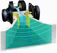
From this image you can see there will be problems in the HF as you have a bend which causes a path length difference. Good news is that using more than one comp on a horn is only needed if you want to cover a very large crowd and we now have better ways of doing this with the Danley combiner (still under patent though so you would have to license for a commercial product).
includes this list which appears to compare the two patents:
Unity Patent - str8aro - High Efficiency Speaker Asylum
haven't had chance to go through this yet.
I should sim this coaxial horn idea I think it can be done just using the LEM module of akabak 3 but I'm spread a bit thin. I would only use a single driver for the midbass and a single comp (probably BMS due to small size and 1kHz crossover point). I think a 10" driver should play up to 1kHz on a horn as long as a simple phase plug is used. I was thinking that output could only be taken from the edges of the cone and a volume filler employed.
Suggestions on theory behind Co-entrant horns?
From this image you can see there will be problems in the HF as you have a bend which causes a path length difference. Good news is that using more than one comp on a horn is only needed if you want to cover a very large crowd and we now have better ways of doing this with the Danley combiner (still under patent though so you would have to license for a commercial product).
includes this list which appears to compare the two patents:
Unity Patent - str8aro - High Efficiency Speaker Asylum
haven't had chance to go through this yet.
I should sim this coaxial horn idea I think it can be done just using the LEM module of akabak 3 but I'm spread a bit thin. I would only use a single driver for the midbass and a single comp (probably BMS due to small size and 1kHz crossover point). I think a 10" driver should play up to 1kHz on a horn as long as a simple phase plug is used. I was thinking that output could only be taken from the edges of the cone and a volume filler employed.
Last edited:
gonna be a stupid amount of diffraction with slots like that though for the LF entry. its the problem with all unity designs. but this looks particularly bad
I'm a bit unsure why the throat reflection stub is less of an issue with this design?
It think it is still an issue, but you can still have that constriction and position it according to the quarter wavelength from the apex rule.
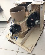
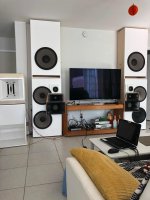
cool setup grec13, whats the lower wave guide near the TV? CMCD of some kind?
so your RH box stock had two 6.5" drivers fed in the vertical slots and you added 2*10" drivers that go into the ports?
Also whats going on with the compression driver mount/throat? it looks very unusual externally.
so your RH box stock had two 6.5" drivers fed in the vertical slots and you added 2*10" drivers that go into the ports?
Also whats going on with the compression driver mount/throat? it looks very unusual externally.
- Home
- Loudspeakers
- Multi-Way
- Renkus Heinz 1996 unity horn patent? US5526456A