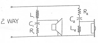
Here is the schematic of a 2-way crossover network. I have a doubt on it. Could anyone help to clarify me, please?
1. For the cone driver section, what is the order of the network? Is it 1st order with impedance equalization circuit or second order with modified slope?
2. What is the responsibility of R1?
3. Someone had told me that the duty of R1 is to modify the slope of 2nd order to be less than 12 dB/octave, was it right?
4. If R1 is definitely a modifier of slope, to be less than 12dB/octave, how to calculate the value?
5. Can R1 and C1 be switched positions to each other?
Thanks in advance
Attachments
Last edited:
I think it depends on the element values and driver impedance whether 1st (with impedance linearization) or 2nd order (with damped Q) we are talking about. So without values it's hard to tell. Acoustically it's even complicated.
It is possible for this configuration to tail off from second order to first in the stop band. I agree that it depends, and simulation would be one way to find out.
Yes, R1 and C1 can be swapped.
Yes, R1 and C1 can be swapped.
Those two can end up being essentially the same thing, depending on how you look at things. One uses impedance equalization so that the rising impedance does not disrupt the slope of the filter. In the second case, the end goal is still to control the roll-off slope. Guessing the specific purpose would need an analysis involving the impedance of the woofer too.1. For the cone driver section, what is the order of the network? Is it 1st order with impedance equalization circuit or second order with modified slope?
In relation with C, it sets the frequency where that leg transitions from mostly resistive to mostly capacitive.2. What is the responsibility of R1?
You use Ohm's law with complex impedances to solve for the transfer function (really just a frequency dependent voltage divider here) then solve for the components' values in terms of your desired transfer function. 😉4. If R1 is definitely a modifier of slope, to be less than 12dB/octave, how to calculate the value?
You use Ohm's law with complex impedances to solve for the transfer function (really just a frequency dependent voltage divider here) then solve for the components' values in terms of your desired transfer function. 😉
I’m confused on this. Could you please give me some examples?
I’m confused on this. Could you please give me some examples?
Frequency and impedance curves are not straight lines, so without knowing these, we don't know what is the acoustical result of an electrical filter applied to a loudspeaker driver.
Here are some examples of a "Zobel" calculator. I have found several different online calculators and some of them give different values for C but usually the same value for R.
HiFi Loudspeaker Design
https://www.the12volt.com/caraudio/zobel-filter-calculator.asp#cc
ERSE - Crossover Calculator - Zobel Circuit
Impedance Equalization (L-Pad) Circuit Designer / Calculator
Speaker Zobel / Impedance Equalization Network Circuit Calculator
One calculator asks for the frequency where the impedance doubles.
It is helpful to have not only the OEM spec sheet (static values) but also a plot of the impedance curve. Usually the Le is measured at only 1 KHz; for much higher crossovers; I would also like to see this measurement at 10 KHz but that is rarely published.
What are these drivers; make, model number, any markings or clues whatsoever???
Impedance Equalization (L-Pad) Circuit Designer / Calculator Help
Another explanation of a "Zobel" impedance compensation circuit.
Another explanation of a "Zobel" impedance compensation circuit.
oldspkrguy, thanks a lot for your information. I think I may know the zobel circuit, but for the question, I’m not sure whether my provided circuit is zobel or not. Please see the attached schematic at original post again.
For the information of the driver, it is commercial speakers, ADS L620.
For the information of the driver, it is commercial speakers, ADS L620.
The driver resistance is 3 ohms.
Driver resistance is mostly irrelevant here, driver impedance is the important parameter, and it is not a constant value. To accurately analyze this crossover you need to determine the drivers impedance curve.
Mike
Well, it would perform that function in that configuration BUT; there may be other reasons why those exact values of R and C were chosen as others have said before me. I am curious; do you know what make or model number these drivers are; are there any markings, numbers, etc???
If you knew what the EXACT drivers were; with some luck; you could find the spec sheets; FR and impedance curves, etc. then zero in on what influence the entire crossover has. Without that information; it's just an educated guess. Does the ADS L620 give these types of details or just a general description???
If you knew what the EXACT drivers were; with some luck; you could find the spec sheets; FR and impedance curves, etc. then zero in on what influence the entire crossover has. Without that information; it's just an educated guess. Does the ADS L620 give these types of details or just a general description???
- Home
- Loudspeakers
- Multi-Way
- What is this resistor used for? (Schematic provided)