Good afternoon, all,
In an apparent disregard for Paul Carmody's guidance to build a proven design as one's first speaker, I'm looking to build my own from scratch.
The particulars in my case are to try and match a Dayton RS225-8 to an SB26ADC in one of the waveguides from SomaSonus (Home | somasonus is his website). I plan to build a ~.5ft^3 sealed box and use a CNC to make a translaminated cabinet.
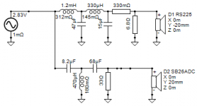
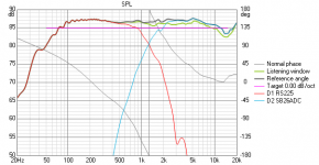
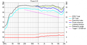
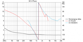
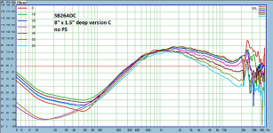
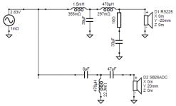
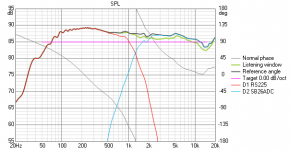
Cabinet aside, I'm looking for feedback on the crossover I've sketched out in VituixCAD. It's a 4th order on the woofer and a 3rd order on the tweeter. It looks like I've matched up the slopes fairly well and based on the FR curves, I think the directivity should match up fairly well at the ~1300Hz Xover region. Schematic and graphs are attached to include the FR from the SB26 in the waveguide from the Soma Sonus website.
With that being said, feedback/criticisms from anyone would be greatly appreciated
In an apparent disregard for Paul Carmody's guidance to build a proven design as one's first speaker, I'm looking to build my own from scratch.
The particulars in my case are to try and match a Dayton RS225-8 to an SB26ADC in one of the waveguides from SomaSonus (Home | somasonus is his website). I plan to build a ~.5ft^3 sealed box and use a CNC to make a translaminated cabinet.
Cabinet aside, I'm looking for feedback on the crossover I've sketched out in VituixCAD. It's a 4th order on the woofer and a 3rd order on the tweeter. It looks like I've matched up the slopes fairly well and based on the FR curves, I think the directivity should match up fairly well at the ~1300Hz Xover region. Schematic and graphs are attached to include the FR from the SB26 in the waveguide from the Soma Sonus website.
With that being said, feedback/criticisms from anyone would be greatly appreciated
Attachments
I have used the RS225 extensively and with typical baffle step loss, it is more like 82.5dB ultimate sensitivity on a 10in wide baffle. It is very wide bandwidth and flat and smooth, so easy to work with.
The response with a waveguide looks great. I made a waveguide coupled RS28F and PTT6.5 woofer and got basically flat and hardly any loss of SPL down to 60deg full angle:
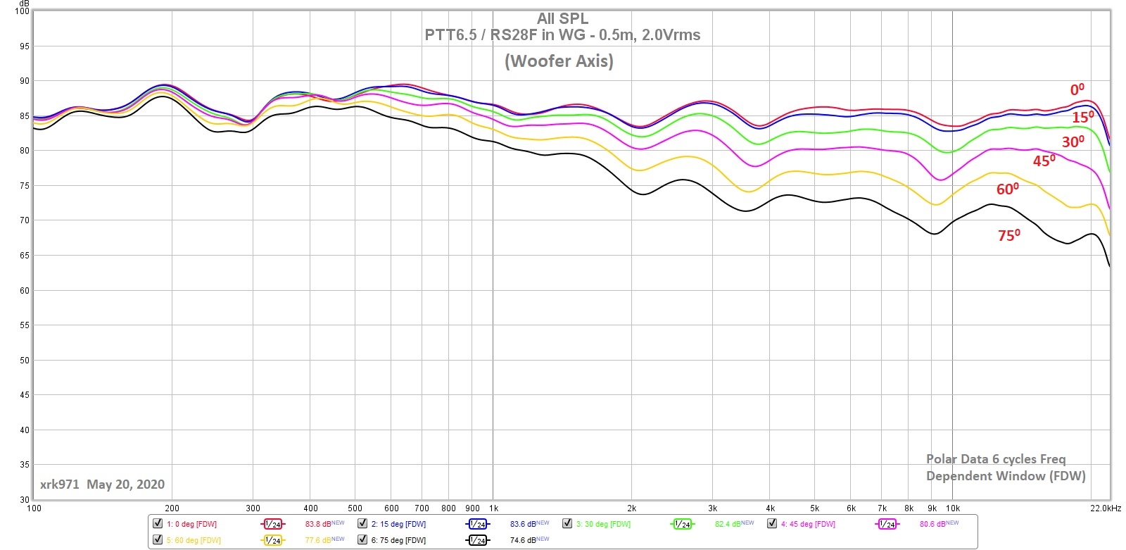
This was with a Harsch XO at 3.5kHz and they integrated together very well in frequency/phase as well as the polars.
The response with a waveguide looks great. I made a waveguide coupled RS28F and PTT6.5 woofer and got basically flat and hardly any loss of SPL down to 60deg full angle:
This was with a Harsch XO at 3.5kHz and they integrated together very well in frequency/phase as well as the polars.
Looks great to me, but I'm biased! If this was a feasibility study and you will measure the actual frequency responses at some point, then I would worry about applying BSC at that time. If you want to model it now, you first must modify the woofers response with the diffraction signature (maybe you already have?), after that you can start tweaking component values to get the flat response you want. BTW BSC is not a discrete circuit to be added.
I think the combo looks really good so far. I wonder how low the SB26ADC can be used?
I think the combo looks really good so far. I wonder how low the SB26ADC can be used?
Looks great to me, but I'm biased! If this was a feasibility study and you will measure the actual frequency responses at some point, then I would worry about applying BSC at that time. If you want to model it now, you first must modify the woofers response with the diffraction signature (maybe you already have?), after that you can start tweaking component values to get the flat response you want. BTW BSC is not a discrete circuit to be added.
I think the combo looks really good so far. I wonder how low the SB26ADC can be used?
Ah, the man himself responds!
So this will certainly start as a 'feasibility study' for me, for sure. I have access to a CNC, so I want to take your waveguide and incorporate it into a solid baffle, if possible. At this juncture of modelling, I'm likely going to have a couple of crossover designs that I will measure with the box. I was looking for a sanity check on what I'm trying to do since I've not done this from scratch before.
Now concerning your "modify the woofer's diffraction response" statement - do you mean adding all of the additional information about listening position, wall locations, etc. in VituixCAD to see what it simulates? If so, I can try that.
And you're right, the BSC doesn't have to be a discreet circuit. I know you can do a parallel resistor/inductor combo but I don't think that's what I'll do here. I've altered the crossover for a ~2dB higher response below ~450Hz. These speakers will be closer to the wall, so I'm going sealed and don't think I'll need as much BSC as many need based on speaker placement.
Attachments
Rather than simulate this, I see you have multiple angular measurements of the waveguide. Why not take the same angles with the woofer so there is no doubt what the baffle is doing. It doesn't matter if you can't get clean measurements at lower frequencies, just nearer to the cross.I'll add in the BSC
Rather than simulate this, I see you have multiple angular measurements of the waveguide. Why not take the same angles with the woofer so there is no doubt what the baffle is doing. It doesn't matter if you can't get clean measurements at lower frequencies, just nearer to the cross.
I think I will buy the stuff for a couple of the different crossovers - one of them with a couple of extra dBs in the baffle loss region and one without - and measure once I make everything.
Eventually I'll make an all-active setup, but that would involve me getting a different AVR for my 5.1 setup and I'm not ready to swap out everything in my setup.
The feedback has been good. Thanks!
 Please try to limit your image size to 1300 pixels wide. Anything wider is trouble for the forum pages.
It sounds like a planwith a couple of extra dBs in the baffle loss region
") .
.For future reference there is more to be gained from this technique than level setting.
Regarding baffle loss, the room makes sure (as does the act of diffraction) that this energy isnt 'lost', hence the tendency to refer to it as 'compensation'.
Although this makes tuning by ear simpler, there is no substitute for the acoustic analysis you are doing nowEventually I'll make an all-active setup,
.- Status
- This old topic is closed. If you want to reopen this topic, contact a moderator using the "Report Post" button.
- Home
- Loudspeakers
- Multi-Way
- Crossover Feedback Requested - 2 Way RS225/SB26 in Waveguide